Aircraft Review | Alabeo C177 Cardinal
Introduction
I was excited when Angelique asked me if I would like to review the Alabeo Cessna 177 Cardinal. I have about 200 hours and an instrument rating in one of its closest cousins, the C172, so I went looking for some more information – only to find that it is indeed very unique and has a well connected and exclusive on-line club of owners that share their experiences and passions for this beautiful aircraft.
It was in the mid-1960’s and the C172 was selling very well as a basic training aircraft. Wikipedia tells us that Cessna engineers were asked to create a “futuristic 1970’s” version of this venerable aircraft. The resultant aircraft was first introduced in early 1968, and was originally designated the C172-J. Designed to replace the existing C172, there was considerable resistance by the company’s Marketing department when the time came for the transition- resulting in the continuance of the C172 and the rebranding of this new aircraft as the Cessna-177 Cardinal. The C-172 remains in production to this day.
The new aircraft came with many new features. The initial model came with a cantilevered wing which lacked the struts of the 172, and a new laminated aero foil. With no struts for support, Cessna added some internal strengthening to the wing, also adding weight to the aerofoil. Another feature was designed to give an unobstructed view when making a turn by placing the pilot ahead of the wing (many real-world pilots will have started with either the C152 or C172, and will be well aware of the need to lift a wing to see what’s in that direction prior to starting a turn).
However, when that moved the center of gravity too far forward in relation to the center of lift (which makes the aircraft hard to rotate at take-off, and flare in a landing, as well as making the aircraft less stable and prone to vertical oscillations known as “porpoising”), Cessna engineers then used the significantly lighter Lycoming-360 engine, a 4-cylinder replacement for the C-172’s 6-cylinder version.
When that still didn’t fully resolve the problem, they then replaced the horizontal stabilizer and elevator assembly with a stabilator (I have described the stabilator is my notes at the end of the review, for those that wish to have more information). As the wing structure was now behind the pilot, this allowed for a streamlined raked windshield, since it is placed between the leading edge of the overhead wing (now behind the pilot) and the forward limit of the cockpit.
Soon after the delivery of the first Cardinal’s dealers and customers started to complain about two keys issues. One was that the Cardinal didn’t handle like the C-172 (although it was marketed as such). You have to really try to have an incident with the C-172, it’s just so stable- at the expense of performance. Cessna engineers soon realized that they had created a “172 on steroids”, and pilots had to actually watch how much aft pressure was put on the yoke or there would be a tail strike, or hard to control “porpoising”. Realizing their error, Cessna offered changes at no charge to new and existing aircraft, mainly around the stabilator. This was not an Airworthiness Directive (AD) and was therefore not mandatory.
CessnaFlyer.org tells us: ”About 1,100 Cardinals were sold at the gala world introduction in Wichita, where dealers were able to take same-day delivery on their new airplane and fly it home to show to customers. There was just one problem. As nearly every airplane took off from Cessna’s Delivery Center, it popped into the air, then dipped back toward the runway and continued to porpoise over the horizon toward an uncertain fate. Not surprisingly, it was the same problem that had confronted service test pilots that was now being experienced by the people who were ultimately responsible for selling the airplane. A stabilator replacement program ensued, whereby a unit with leading edge slots was installed to increase landing authority, but the damage had been done. …… The Cardinal’s fate was sealed the first time the first dealer struggled off the ground on that 90-degree day in Wichita and porpoised over the horizon”. More information can be found via this URL.
The other issue was that the Cessna-177 appeared to be underpowered with a 150 hp engine (which the then current models of the C172 came with). Incorporated into the Cessna-177-A model (sold in 1969) was an uprated engine from 150 hp to 180 hp.
The Cessna-177-B was released in 1970 (one of the two models included in this Alabeo product), and featured a constant speed propeller and a new wing aerofoil. The final aircraft in the line was the Cessna-177-RG, released in 1971 (also modeled in the package) with retractable landing gear. To counter the additional weight of the electrically powered hydraulic system to operate the landing gear, a new 200hp engine was added, along with an electric fuel pump for priming the engine (unlike the -B model that requires manual priming), and is fuel injected (removing the need for carburetor heat, as in the -B model).
This was the highest performing model in the Cessna-177 line, with a cruise speed of 148 knots (there were enhancements to the -RG model later such as a 28 volt electrical system). With a 200 hp IO-360 engine, the RG could cruise 80 percent as fast as the C-210 for 60 percent of its purchase price, and of all the Cardinal models sold from 1968 through 1978, half were RGs. A total of 1,543 Cessna-177-RG models were delivered from Cessna and their subsidiary Reims in France.
Under FAA flight rules a “high performance” endorsement is not required, since that applies to engines over 200 hp. However, the retractable gear and constant speed propeller would require a “complex aircraft” endorsement.
There was a total of 4,295 Cardinals built between 1968 and 1978. While the demand at the time wasn’t strong enough to sell more of them, it has become a niche aircraft with a strong following.
Researching this aircraft, I have found references to it as “177”. “C-177”, “Cessna-177”, “Cardinal-177” and other names. I have used the term “Cessna-177”, and occasionally just the term “Cardinal”. Other aircraft I refer to are abbreviated to “C-172” (Cessna 172), “C-152” (Cessna 152), “C-210” (Cessna 210) and “C-182 (Cessna 182).
I have included some links to articles featuring the Cessna-177 for those that wish to further explore this unique aircraft.
- http://www.askacfi.com/12316/transition-c-172-to-c177rg.htm
- http://www.cardinalflyers.com/prep/specs/177b2.php
- http://cavok.hu/wp-content/uploads/C177_AFM.pdf
- https://en.m.wikipedia.org/wiki/Cessna_177_Cardinal
- http://cardinalflyers.com
- http://www.bordenflyingclub.com/sites/default/files/1971-C-177B-POH.pdf
- https://www.aopa.org/go-fly/aircraft-and-ownership/aircraft-fact-sheets/cessna-177-cardinal
And for those that wish to know more about a constant speed propeller:
- https://www.flyingmag.com/technique/tip-week/constant-speed-prop-basics
- https://www.aopa.org/news-and-media/all-news/2015/june/flight-training-magazine/technique–constant-speed-propeller
Stabilator
Many conventional aircraft have a fixed vertical and horizontal stabilizer near three rear of the fuselage, and mounted to them a moveable rudder and elevator respectively for controlling patch and yaw attitudes.
The Cessna-177 has the conventional vertical stabilizer and rudder, as described above. However, the horizontal stabilizer and elevator (separate components on conventional aircraft as described above) are just one component that is moveable- there is no fixed portion. This obviously increases the moveable section surface area considerably, giving it much more authority- particularly at slow airspeeds.
Installation and Documentation
Installation is very straightforward. I downloaded the aircraft from the Carenado site, where I could clearly see and copy the key. The aircraft folder is simply placed in the X-Plane 11 Aircraft folder. Activation was very easy, offering the option to paste the key into the activation screen, after which I had to reload the aircraft. If you’re purchasing from the “.org” store, this may have a slightly different activation window.
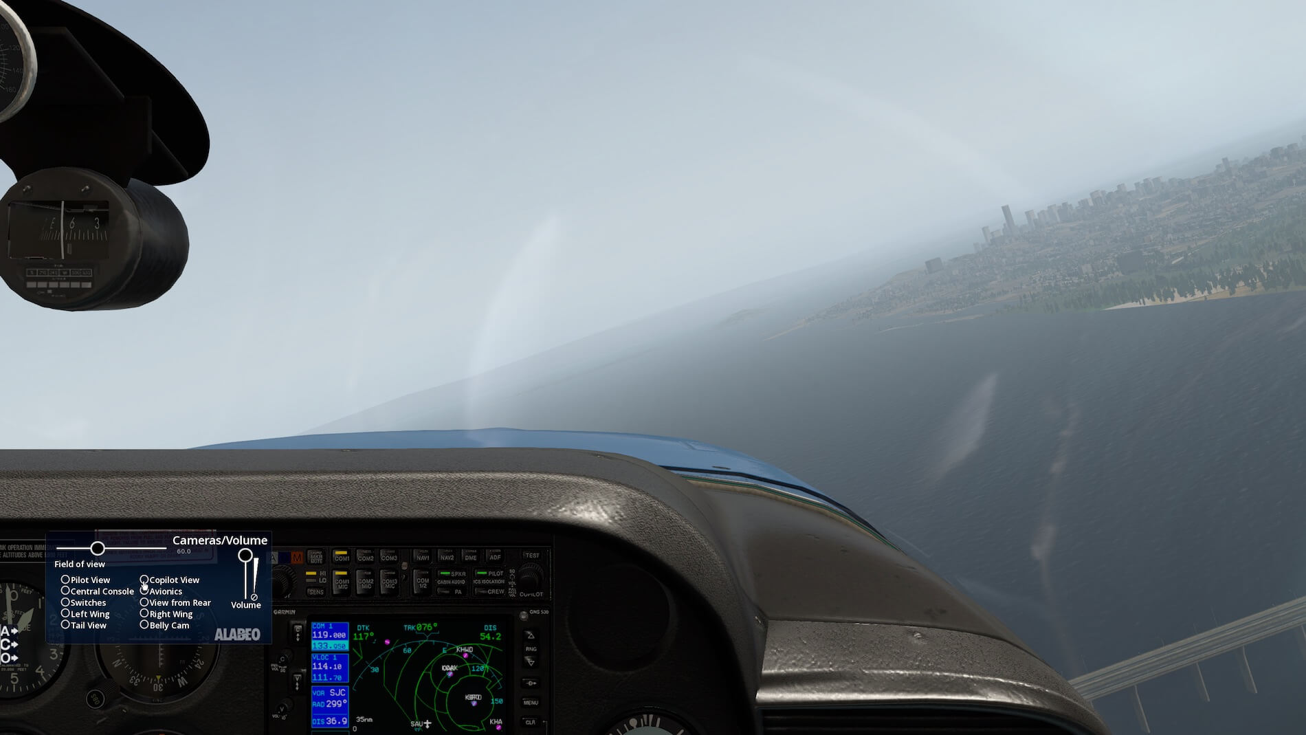
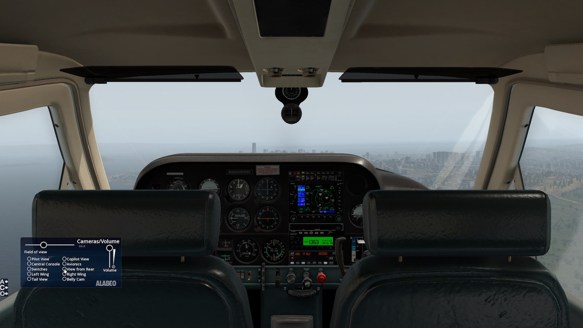
“Out of the box”, the “quick-look” functions were assigned to ten viewpoints including pilot, co-pilot (front seat passenger), rear seat passenger, avionics, switches and external views showing wing, tail and belly. Three on-screen menus are visible on the lower left. One invokes a 2-D auto-pilot, another is preset views (the same as the ten default “quick-look” views above) along with FOV and sound volume.
Thanks to Daniel Klaue at Carenado, for explaining some more info to me on these menus. You can fade the “A”, “C” and “O” tabs out with the mouse wheel. Also the camera snap points can be re-labelled (if you want to change the views through the X-Plane 11 “quick-look” key assignments). This is done by editing the Manifest.JSON file in the aircraft folder- just back it up first. For further information on editing this powerful file please see this post.
I would have liked to see a 2D window of the MP, RPM and Fuel Flow, since this information is critical to precision flight as is required on an instrument flight plan. An Options on-screen menu is also featured which includes window and instrument reflections, a change in livery and opening of various doors.
I should add that the included liveries are assigned to both the -B and -RG models, and selecting a livery will assign the respective model to it- a nice feature. The -RG liveries include the suffix “-R”.
Documents are supplied for both featured models and include Emergency Procedures, Normal Procedures and Performance. For the -RG model offered are cruise performance tables arranged by RPM, Manifold Pressure and Temperature. These are displayed over 6 pages for cruise altitudes between 2,000 and 12,000 feet. They are important to plan endurance (fuel flow) and True Airspeed- the latter critical to instrument flight to calculate EAT at waypoints.
For the –B model, this same information is displayed for ISA temperature only and for 5 altitudes from 2,500 feet through 12,500 feet, in multiples of 2,500 feet. This difference would appear to be a change in Cessna’s POH format. Missing for both models is the time, fuel burn and distance to climb to cruise altitude, CG graphical calculator and take-off and landing runway length data by gross weight.
However, I understand that some of this data is not utilized by all sim pilots. For the -B model the Normal Procedures have speed in mph, and Performance in KTAS, presumably reflecting the change from mph to knots in the Cessna POH. Also included for both models are documents showing auto-pilot operation and joystick / graphical recommended settings.
The auto-pilot document describes most of the available functions (which have been simplified from the actual KFC-225 Bendix-King unit for simplicity of use). The only function missing in the auto-pilot documentation is the Altitude knob, and how Vertical Speed interacts when the selected altitude is captured (we explore that later in flight tests).
Finally, prior to looking at the features of the model and some flight test data, I unrealistically took off in the –B model, climbed to cruise, then changed in-flight to the –RG model, to get a feel of the change in flight dynamics. I was pleased to see the RG model drop the nose reflecting the higher weight of the 200 hp engine.
External Modelling
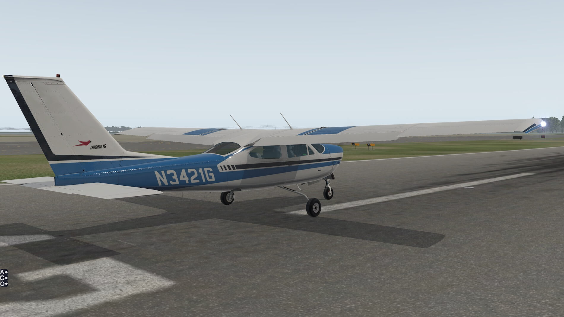
In looking at the external views of this beautiful aircraft, I somewhat unrealistically set the Cessna-177 RG on runway 12 at KSQL. Now, it’s not the safest place to put an aircraft without engines running, and at this towered airport I am sure that I would have a visit from the Flight Standards District Office (FSDO), that person who you never want to see at an airport (although I know of several and they are nice people!).
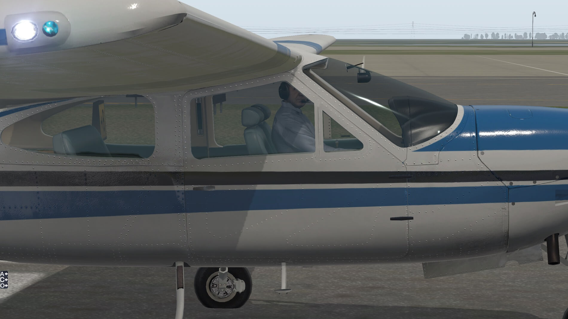
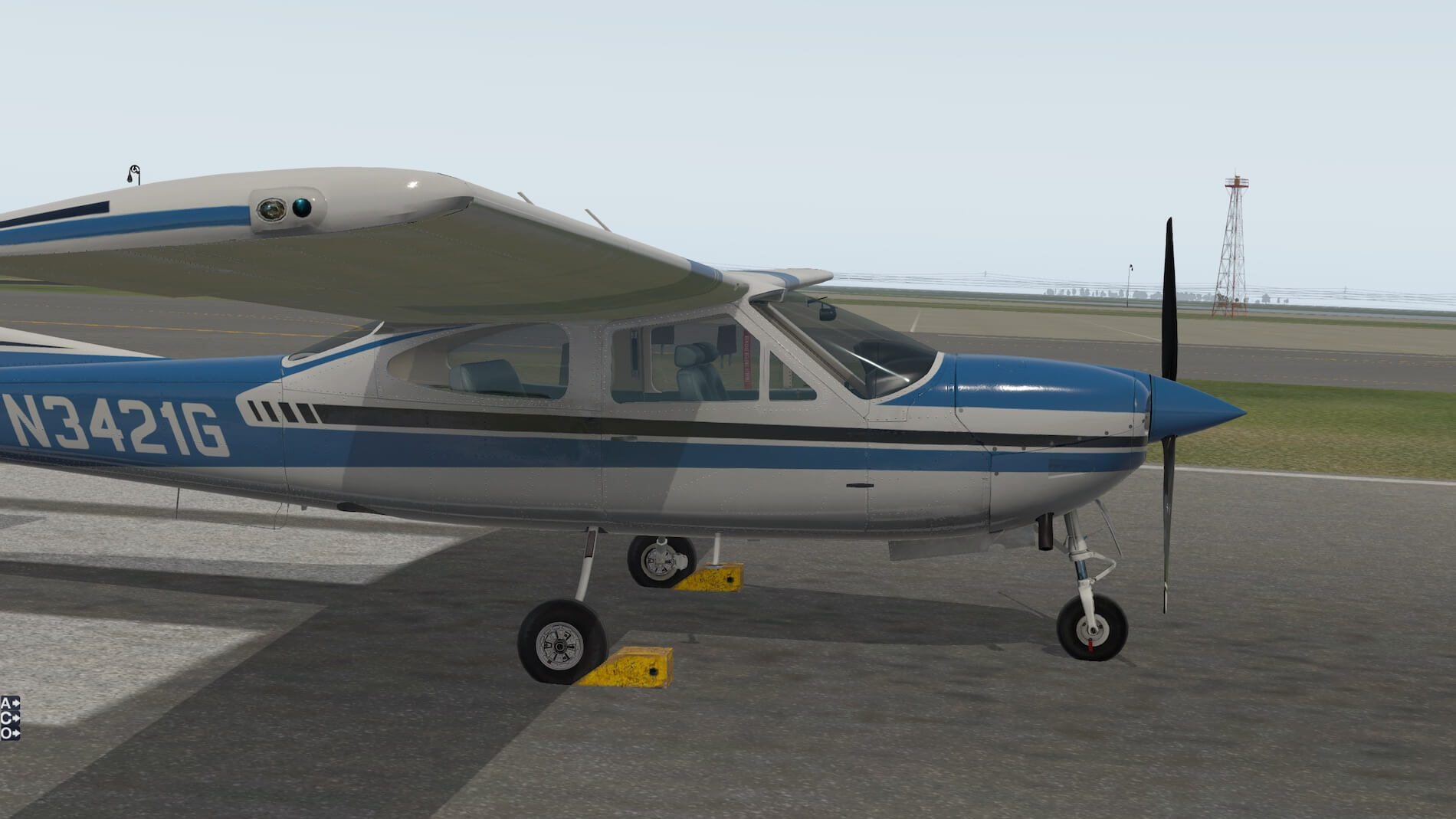
Looking first at the Cessna-177-RG, the windows have an opaqueness that is realistic (maybe some scratches might make it more so). The first screenshot is taken from the port side front, and shows the enormous doors that this aircraft is known for (both the door size, cantilevered wing and the gear retraction mechanism make this aircraft closer to the C210 than the C-182 or the C-172 that it was originally derived from).
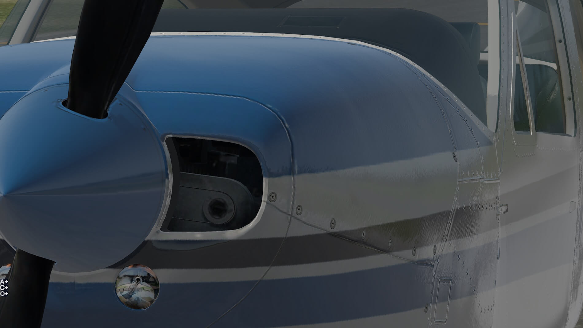
Note the exterior panels are well delineated as are the rivets and screws. I then took a look at the engine (port side front then front). You can see the engine components quite clearly, as well as the propeller spinner (some scratches and marks would make this look even more realistic). Another view from the starboard front at a distance showing the neat chocks and pitot cover with the engine stopped. I love the wings on this bird.
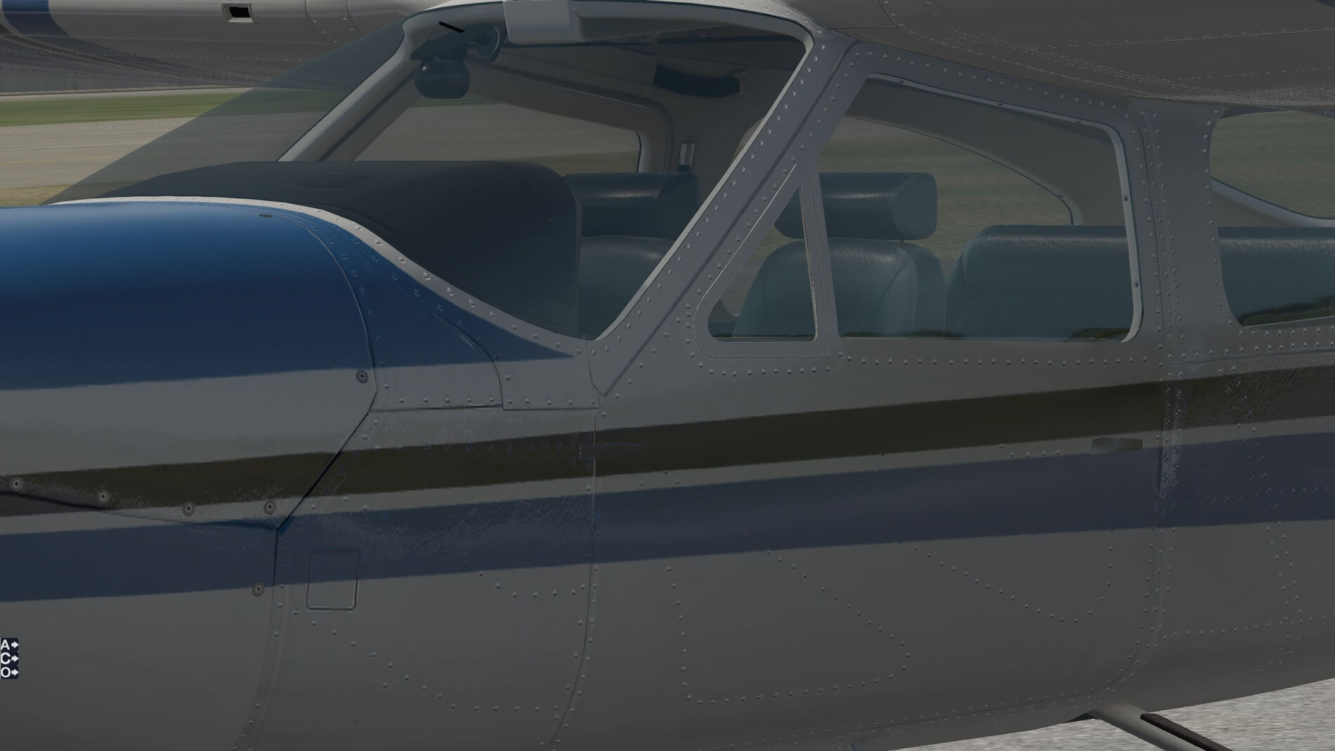

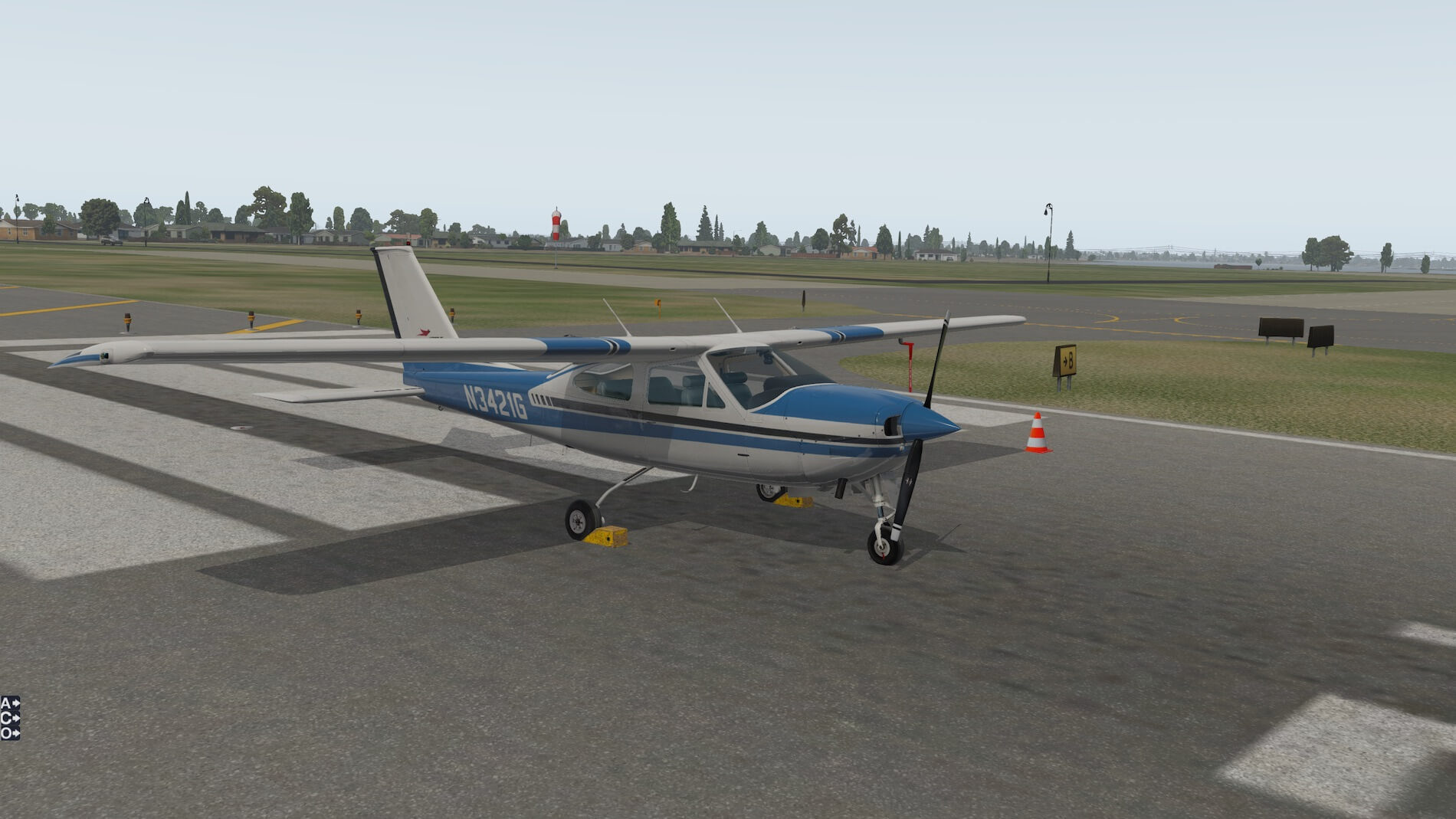


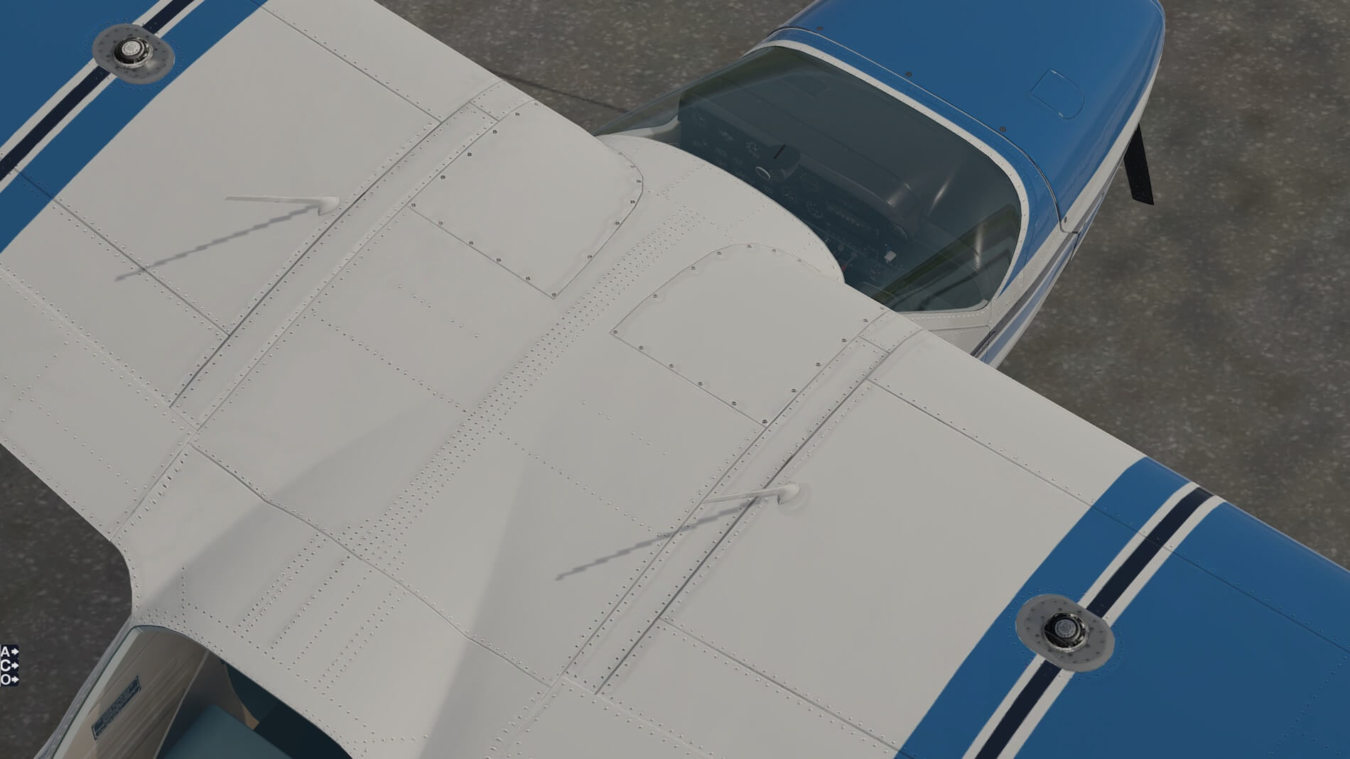
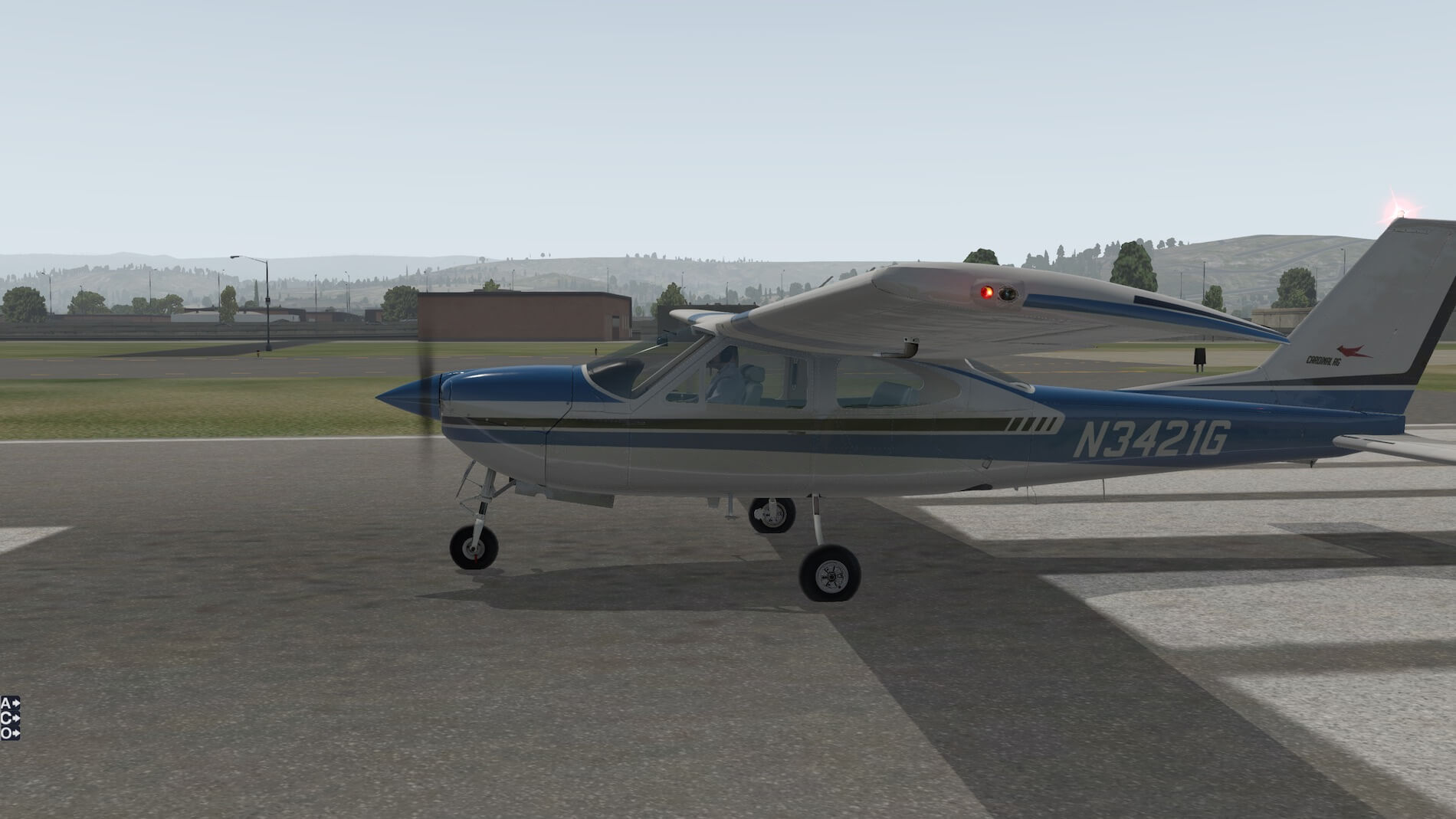
The strobe and starboard navigation light are well done and very visible when turned on. Looking at the port side showing the pitot cover, a port rear elevated view shows the detail on the upper surface of the wings. Another top-down view shows the detail around the fuel tank caps (left and right), as well as the wing root inspection covers and VHF radio antennas. The sloped windshield discussed previously can be easily seen here.
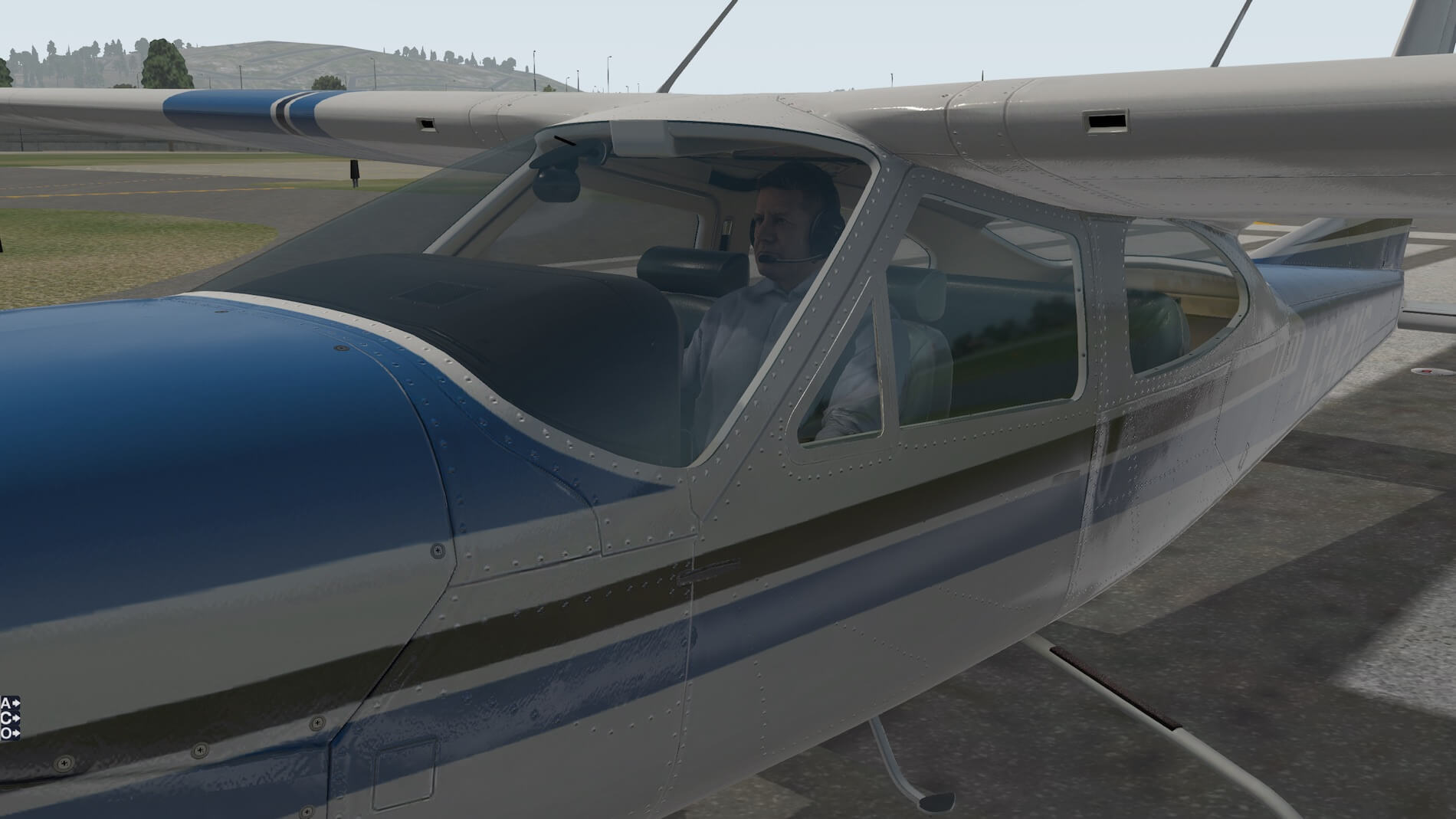
Now with engines running, a look at the port navigation light and the landing and taxi lights on the nose of the aircraft. When the engines are running a pilot is visible- a very well done image. Usually he looks towards the front, but occasionally looks at our external location- until we position ourselves behind the aircraft where he only looks downwards at the flight instruments.


Finally a view of the flaps at full extension. I would note that in a later section we show the undercarriage retraction sequence in 3 screenshots. This is a beautiful rendition of a cool aircraft.
Next we take a look at the -B model where the undercarriage is fixed, showing the flared wheel pants.

These are well done and show the detail that goes into making the fixed undercarriage more streamlined.
Internal Views
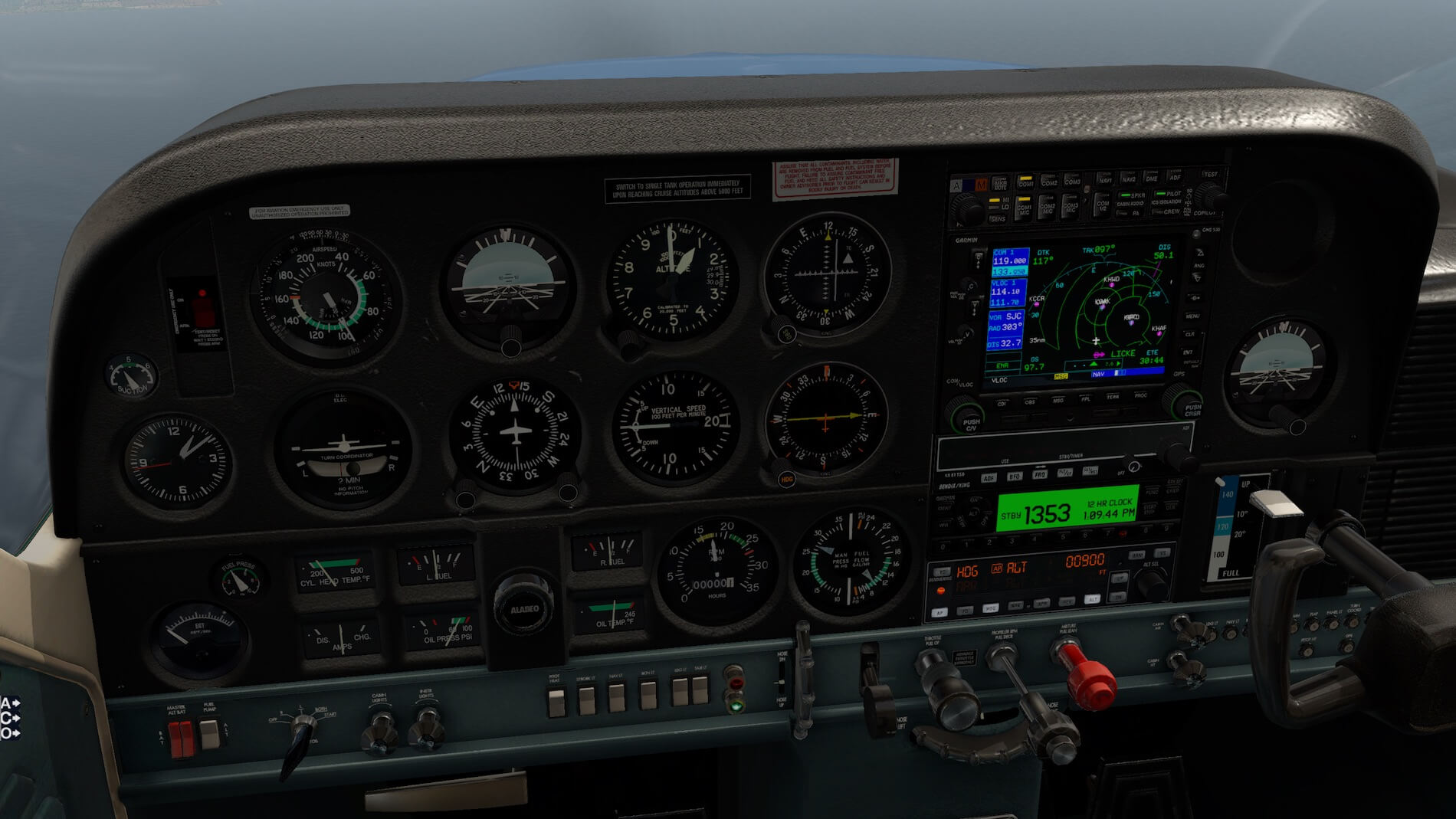
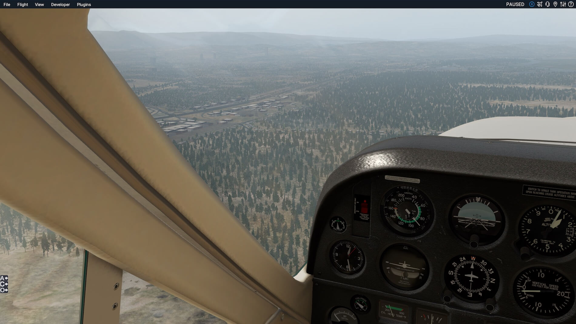
Firstly, I have shown the custom internal views that come with this aircraft.


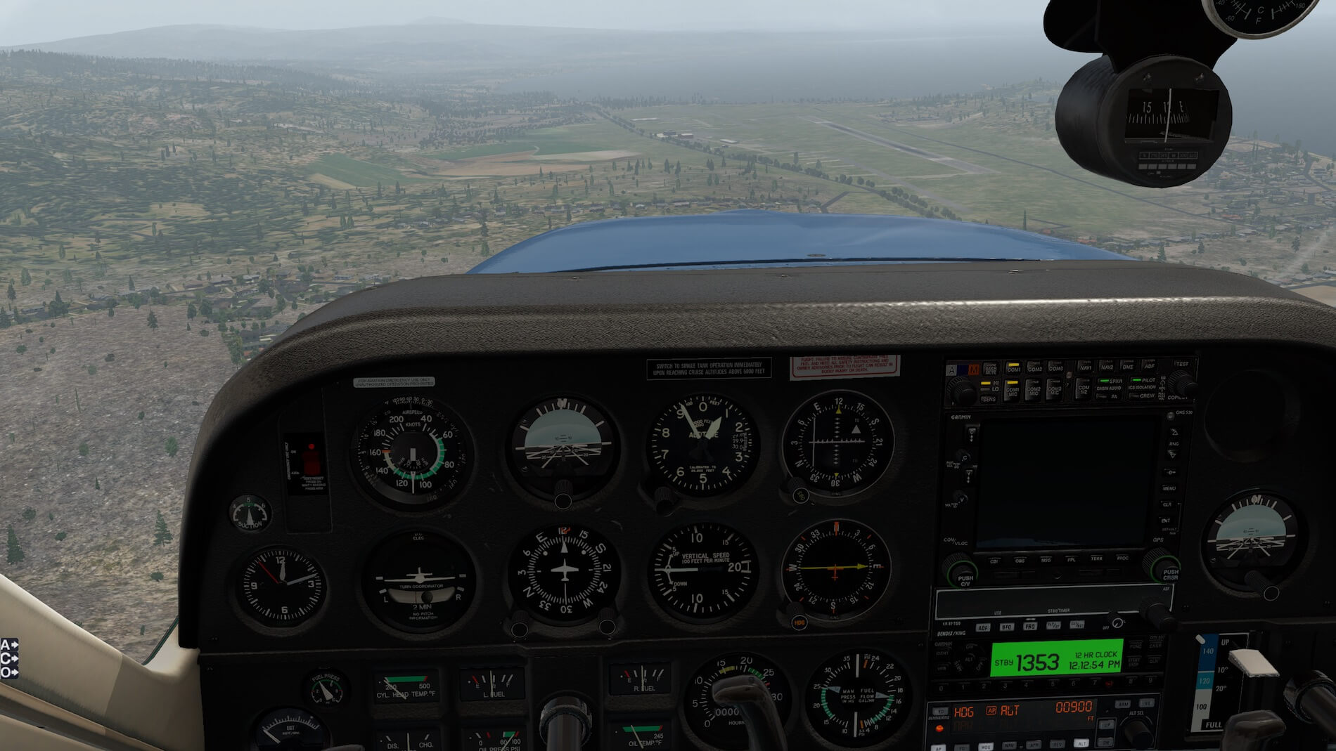
I have made my own “Pilot view”. Since these are actually quick-look views they can be easily changed. Since I like to look at the engine gauges as well as the second row of instruments (including the Heading Indicator which is very important), I have changed my “Pilot view” to show all of these plus the forward outside view.
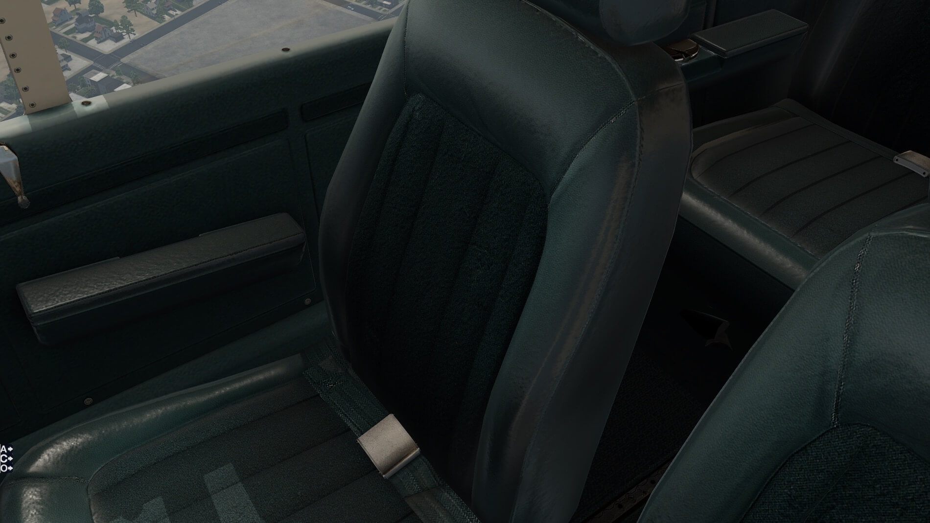
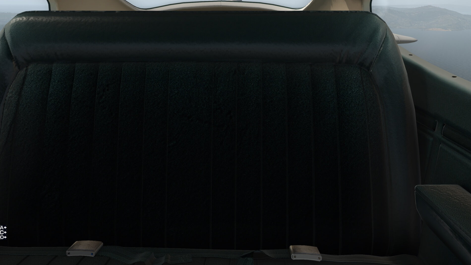
I also moved the camera around to show the copilot and rear seats and the baggage area.

Finally, some night views.
Firstly, the custom “Pilot view” with gauge lighting, then a full instrument panel view also with gauge lighting, and finally adding flood lighting.

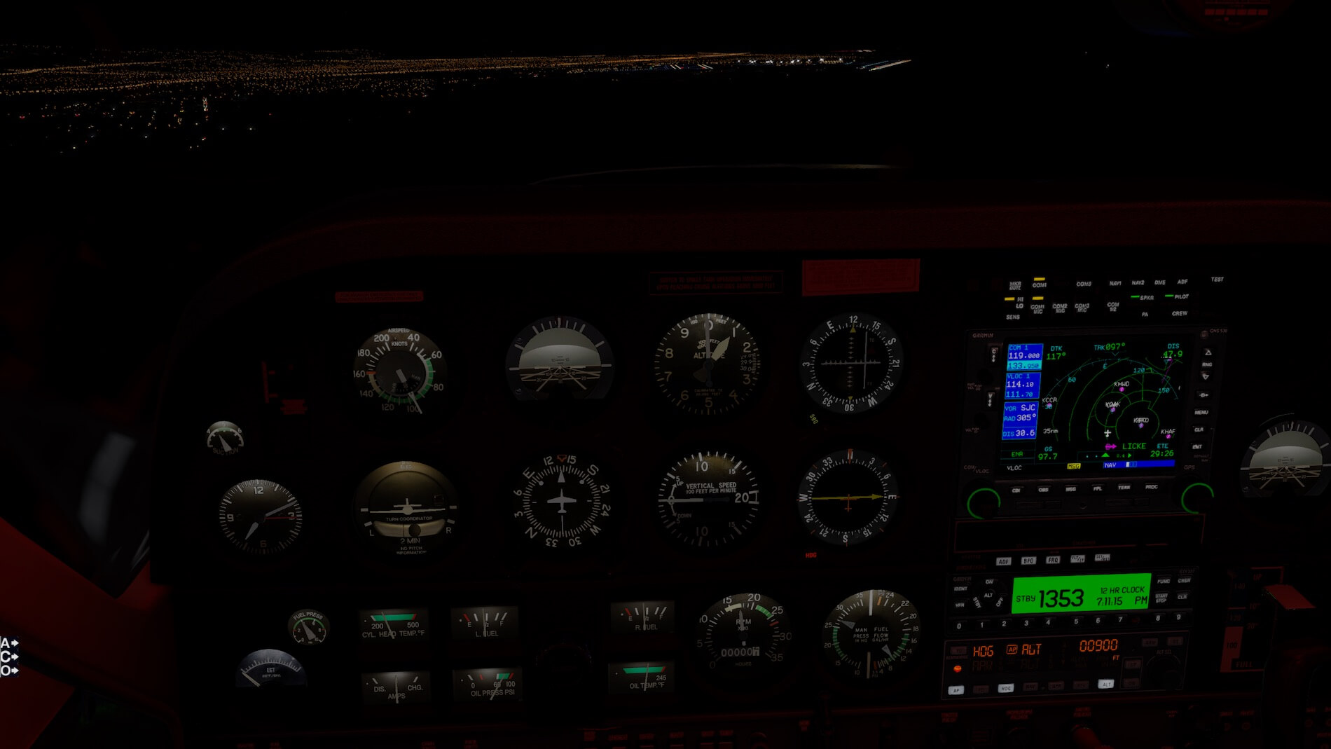

The yokes can be hidden by clicking on the base. I love the shadow effect and reflections, they are very well done and add to the realism. A lot of time has been put into the detailing of the interior and it shows.
Systems
The systems and avionics on this aircraft are the basic “six-pack”, similar to what is offered for the XP11 C-172. Only one VOR display is included that would potentially make it more difficult to reference an intersection of two VOR radials (it can be done with one VOR display but requires switching back and forth).
Additionally, since the FAA requires that the instrument required for instrument approaches (this would be the VOR display for an ILS approach) cannot be switched in certain portions of the approach, fixes that define step-down procedures that require dual VOR systems would be unavailable, or may require radar. There is, however, an ADF, although many NDB’s have been decommissioned. And in more recent years GPS has added enormous functionality in being able to define any type of fix, as long as the GPS is programmed correctly.

I looked on-line and found a number of Cessna-177’s for sale. I found one that definitely had two VOR displays, although no ADF, so I assume that some after-market changes were made to add functionality. I even found a reference to an HSI being fitted to the aircraft, as quoted here from cardinalflyers.com; “Just to give you an idea of what can be done, I have King KY-97 comms, KNS-80 and KN-53 RNAV and nav, the digital ADF and Xponder, IIMorrow 618, Argus 3000 driven by a Motorola GPS, HSI, Insight GEM and Strikefinder, Davtronics voltage/temp and clocks, a S-Tec 60-2 3-axis autopilot with altitude hold and digital preselect, electric trim, Shadin miniflow-L fuel flow computer, Stereo intercom with a 10 disk CD changer and a UHF FM Ham radio hardwired in. It all fits the ’76 panel and runs fine under the 50 amp 12 volt system.“ For more info see this URL.
Sounds
In desktop simulation we lack the sensation of movement and it’s associated spatial perception, and often the feedback to the flight controls from the control surfaces that make the aircraft appear as a “living thing”. I have long believed that realistic sound makes up for some of this deficit and this aircraft by Alabeo does very well from that perspective.
The propeller sound, particularly when changing pitch, is very well done. There is a lot of rumble from ground movements, and wind noise when in the air. The model uses FMOD, although I am no expert in that technology. The sound from the engine increases nicely when the doors are opened, and each switch and control have a nice audible “click” that helps in reaffirming that the switch function has been actuated. Wind, ground and flaps/landing gear noises are well represented.
The doors and windows are not able to be opened in flight. I tried to do this as, like I expect every other student pilot flying a Cessna trainer aircraft, my CFI one day opened his door in flight to ascertain my reaction. The wind noise is huge when that occurs, and I panicked- only to learn from that experience that I need to fly the airplane first, and read the POH where it plainly states that the aircraft is flyable with the door(s) opened.
Flight Experiences : Short Flight -B Model
I have used some abbreviations in these flights.
MP = Manifold Pressure
KSQL = San Carlos, CA airport
KPAO = Palo Alto, CA airport
KSNS = Salinas, CA airport
SJC = San Jose, CA VOR
KIAS = Indicated airspeed
KTAS = True airspeed
For this first short flight I’m using the -B aircraft model to explore the Landing Performance. Before I take this aircraft on a cross country flight- something long enough to explore the flight model and included systems- I thought I would try first a landing.
It’s my experience that landing an aircraft, with the changing configurations as well as the relatively low speed handling, is an excellent way to see how it flies at the edge of the flight envelope. I chose a route that I often flew when I had soloed in the San Francisco Bay Area, from Palo Alto (KPAO) to San Carlos (KSQL) airports. It’s a short flight, about 8 miles.
I was renting a C-152 out of KPAO, but the airport was always busy, so I would “commute” in the aircraft to KSQL where air traffic was a lot less cluttered. Both airports are towered (Class D), so I had to get KSQL ATIS, and contact KSQL tower after being released from KPAO, all within several minutes.

I need to add a disclaimer at this point. I am flying a route that I used to in the early 1990’s. I am unaware if the “Dumbarton visual departure” even still exists. I also note that the reconfigured KSFO Class B may affect the integrity of the altitude and route that I am flying. So, some poetic license if being used in this route. With the advent of RNAV I also note that the route of flight could be KPAO-VPBDX-VPBDZ-KSQL, avoiding a more restrictive Class B segment.
My test with the Cardinal was to climb to 1,000 feet, throttle back to fly at close to 90 KIAS (at a nautical mile and a half for each minute, that’s a little less than 6 minutes on average between airports). I had weather set at “VFR” in the manually configurable weather option of X-Plane 11.
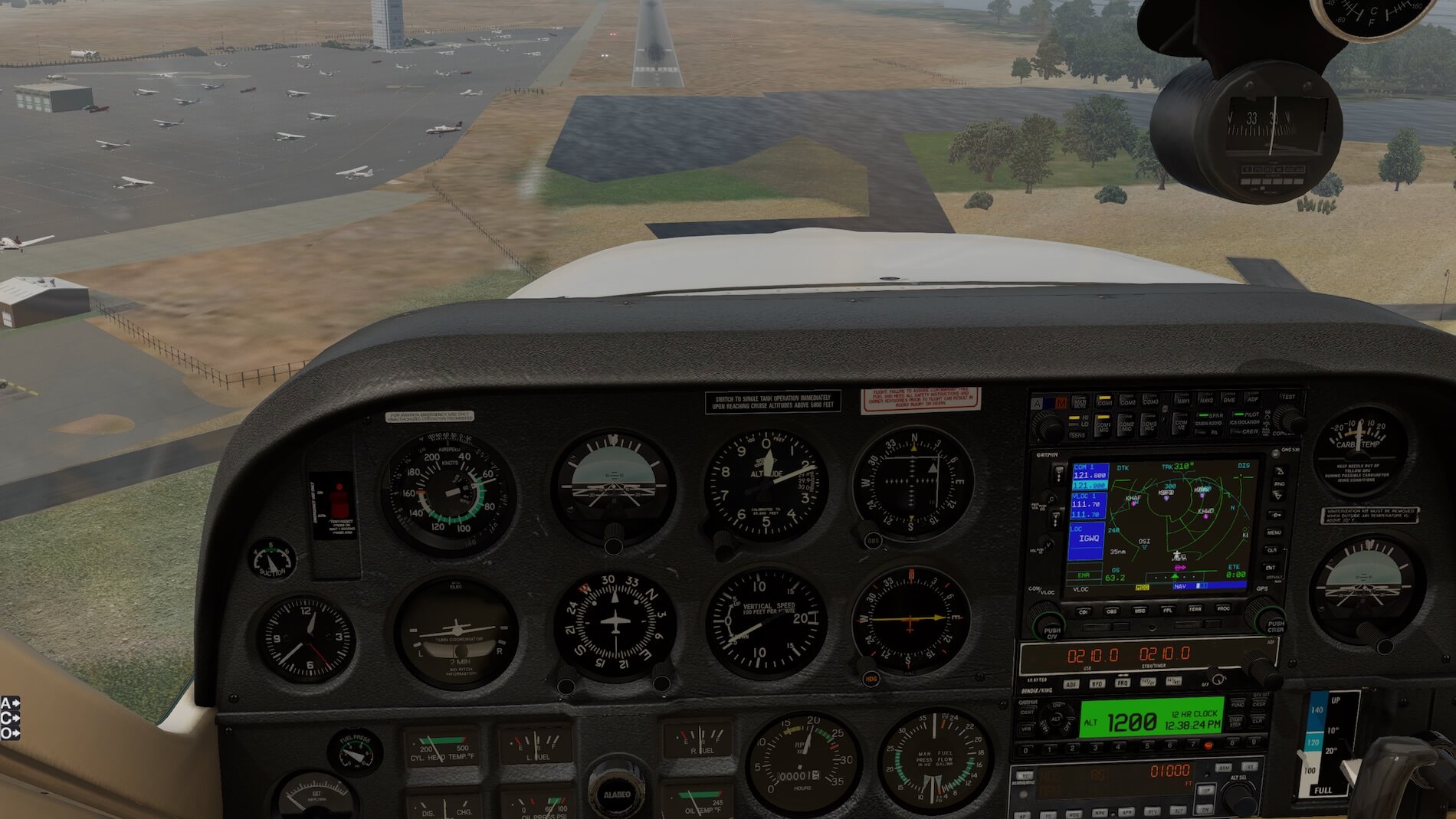
Since the focus of this test is the landing, I started with engines running on runway 31 at KPAO. As with any GA aircraft of this size, take-off is at full power (throttle fully forward) and the propeller pitch set to highest speed (finest pitch), with mixture at full rich. Simply put, all engine control levers fully forward (MP is 27.5 inches, Propeller is red-lined at 2700 RPM, Fuel Flow is 18 gph).
As recommended in the POH we extend flaps to 10 degrees. Rotate speed of 55 Knots is quickly attained, and we rotate into the air. The default trim setting is at center, which results in a climb at just over 1,000 fpm and speed of 85 KIAS after flaps retraction.


The aircraft should always seek the speed that it’s trimmed for, which is realistically represented here. We fly on runway heading until abeam of the Dumbarton Bridge, to the right. Our cruise altitude of 1,000 feet comes up very quickly, so we throttle back to 14 “ of Manifold Pressure (MP), and reduce prop speed to 2400 RPM, tweaking our MP back to 14” after setting the propeller speed.
The aircraft’s nose drops immediately after setting cruise power, if left alone the aircraft will enter some damped oscillations as it once again seeks 85 KIAS. In order to stabilize the aircraft, I pitch the aircraft with the yoke to obtain 85 KIAS, which is the trimmed speed. We need to act on these settings when at no higher than 900 feet MSL or we will bust our cruise altitude.
While not on an instrument flight plan and needing to be at the correct altitude within 50 feet, we do need to be aware of the overlying Class B airspace for San Francisco (KSFO). Unauthorized entry into the Class B can result in license suspension or worse.
Passing the Dumbarton Bridge to our right, we now fly a heading of 270 (West), this will take us close to the southern end of KSQL. We want to remain north and east of the highway we see on our left and are roughly paralleling, which is US 101. Here’s where you would get handed off to KSQL Tower and would need the ATIS prior to contacted the tower.
So, we’re still trimmed to 85 KIAS, not exactly at 90 KIAS as I had planned, and if this was a longer flight I would trim for that speed. I’m impressed by the “heavy” feeling and stable flight model, and how quickly it stabilized. While I haven’t flown the real C-177 it behaves like a C-172 “on steroids”, and is as stable as the 172 in flight.


This is not due to re-trimming the aircraft, but rather to the fact that the flaps extension has changed the aerofoil in such a way that it alters the trimmed speed. Since the Normal Landing procedures show a landing speed with flaps extended of 70-80 mph, which equates to 60-70 knots, I’m right in the middle of the desired landing speed.
I also tried re-trimming the aircraft to a lower landing speed, but found- as I suspected- that the aircraft quickly becomes nose-heavy as airspeed is reduced, and has trouble entering the desired flare attitude, or stalls prior to attaining that same flare attitude. As in most aircraft, as performance is increased the adherence to published airspeeds becomes much more critical.
I am impressed with the stability of this flight model. While I haven’t flown in a Cessna-177, I would expect the real aircraft to exhibit a similar stability to the C-172, from which it was originally derived. It is a fast airplane and so inherent stability makes it easier to stay ahead of the aircraft.
Flight Experiences : Longer Flight with AP
This longer flight takes us from San Carlos (KSQL) to Salinas (KSNS), so we plan to use the auto-pilot on most of the route. This is an instrument flight, and while it would be fun to write up realistic details of how these flights are planned and flown, that is beyond the scope of this review as it is for the aircraft specifically. I check the Departure Minimums at KSQL:
TAKEOFF MINIMUMS: Rwy 30, N/A- obstacles and ATC. Rwy 12, 300-1 3⁄8 or std. w/min. climb of 240’ per NM to 300.
DEPARTURE PROCEDURE: Rwy 12, climb heading 120° to intercept SJC VOR/DME R-281 to SJC VOR/DME before proceeding on course.
On the day of flight we find KSQL is using runway 12 at KSQL, and file a flight plan: KSQL-SJC-V485-HENCE-KSNS, at 5,000 feet. It’s a relatively short flight for the Cessna-177. In our very brief details of an instrument flight I must stress the importance of anticipated timing at our flight plan waypoints. In the IFR flight plan we need to state what our cruise KTAS (true airspeed) will be, and the ATC system will use that to derive the ETA at our various waypoints in case air traffic management is required.
On page 4 of the document “C177RG Performance” we find “the numbers” for flight at 6,000 feet. We chose 5,000 feet as our route of flight is east-bound, between 000 and 179 degrees. I would probably interpolate the charts for 4,000 and 6,000 feet, but I’m being quick and brief here so I’m just using the 6,000 feet numbers. Temperature is standard, so we use the middle column.
I pick a MP of 23” and 2300 RPM (known as “23 squared” in aviation talk). This will give me a true airspeed of 140 KTAS and a fuel flow of 9.6 gph. The entire flight is about 80nm, including anticipated radar vectors to the RNAV approach to runway 13 at KSNS. I calculate that the flight will take about 35 minutes at cruise speed, although the initial climb sequence will be at a lower speed. (In actual flying I would make use of the distance/time/fuel for the climb to 5,000 feet, which would in effect be my “top of climb” and where this cruise performance information would start from.)
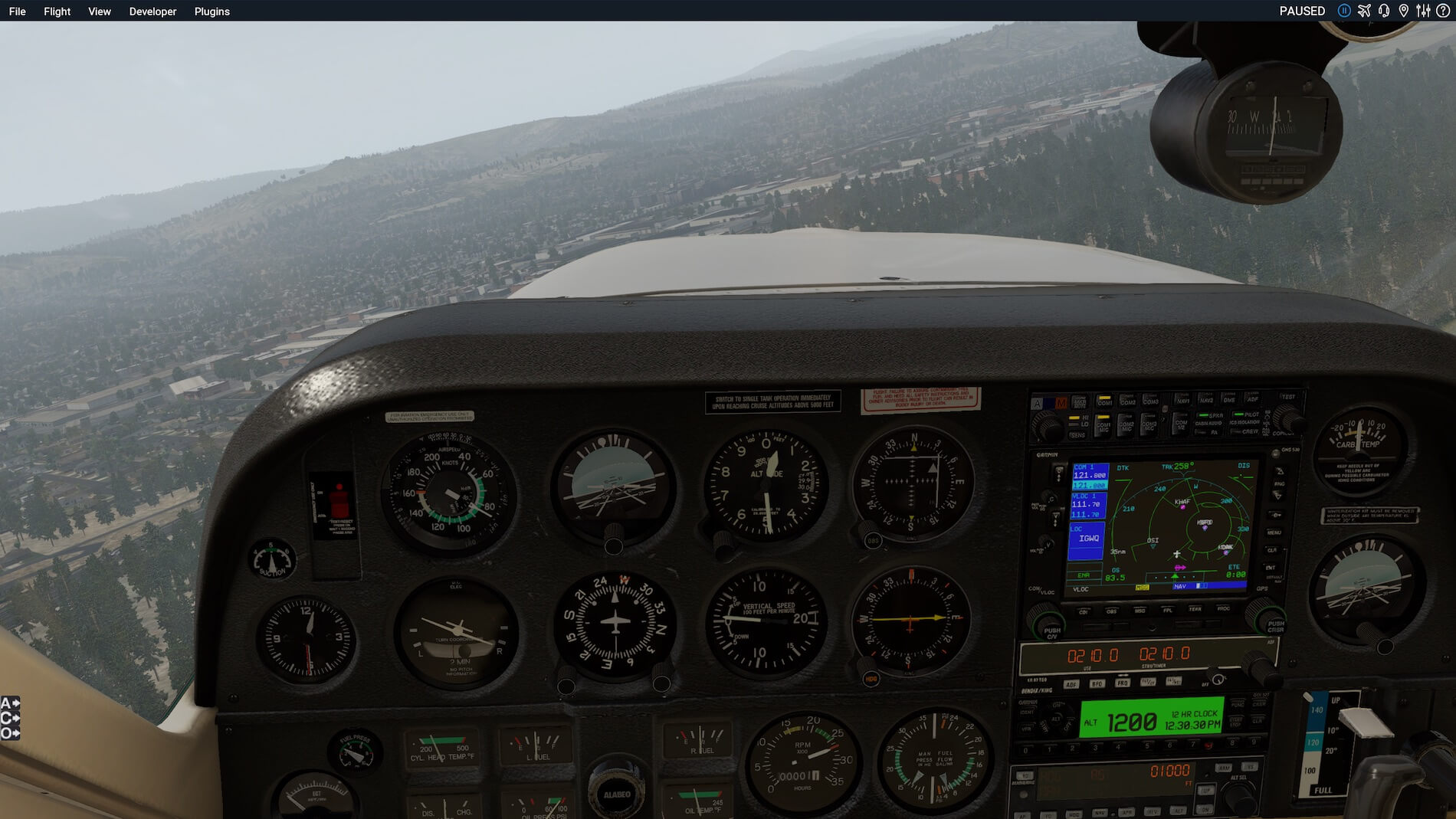
On this flight we will be using the Cessna-177-RG model, engines off. Notably, as well as have retractable gear, it also features a 200 hp engine which is fuel injected (so we don’t have to worry at carburetor heat).
It also has an electric fuel pump for priming the engine, as well as a “full panel” that extends all the way to the right fuselage skin (earlier models used a “half panel” that had a “featureless portion” on the right side).
We arrive and pre-flight the aircraft. We have a tank full of fuel so no issues with the required endurance, and the weather does not require the use of an alternate, so our only contingency is 45 minutes at cruise beyond the planned flight.
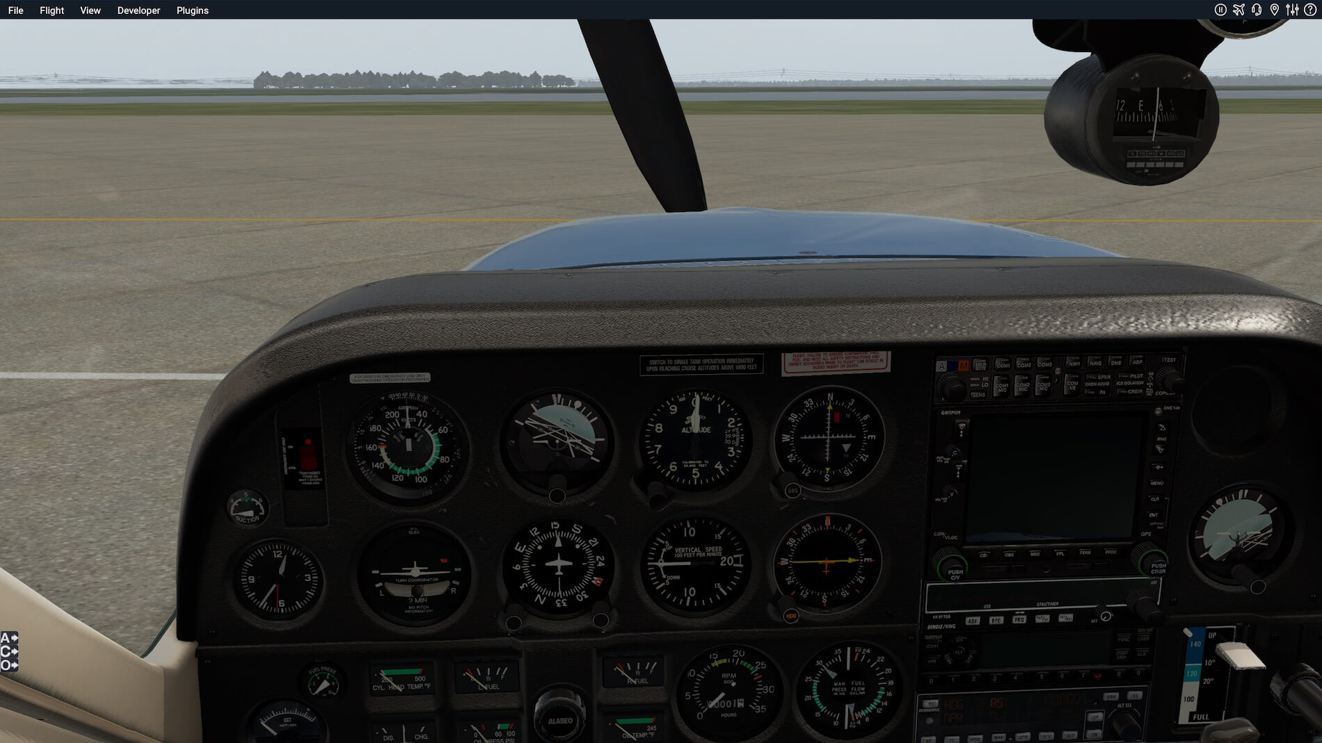
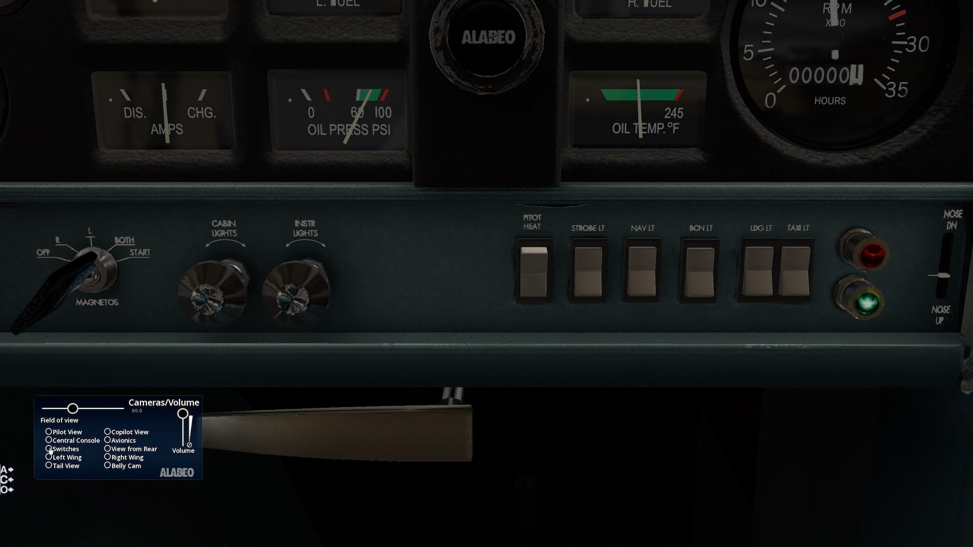
I have started the engine using the methodology in the “Normal Procedures”. If you haven’t done the other pre-flight checks, make sure that you set the fuel valve to “Both”. You will also need to set the Heading Indicator to the magnetic compass.
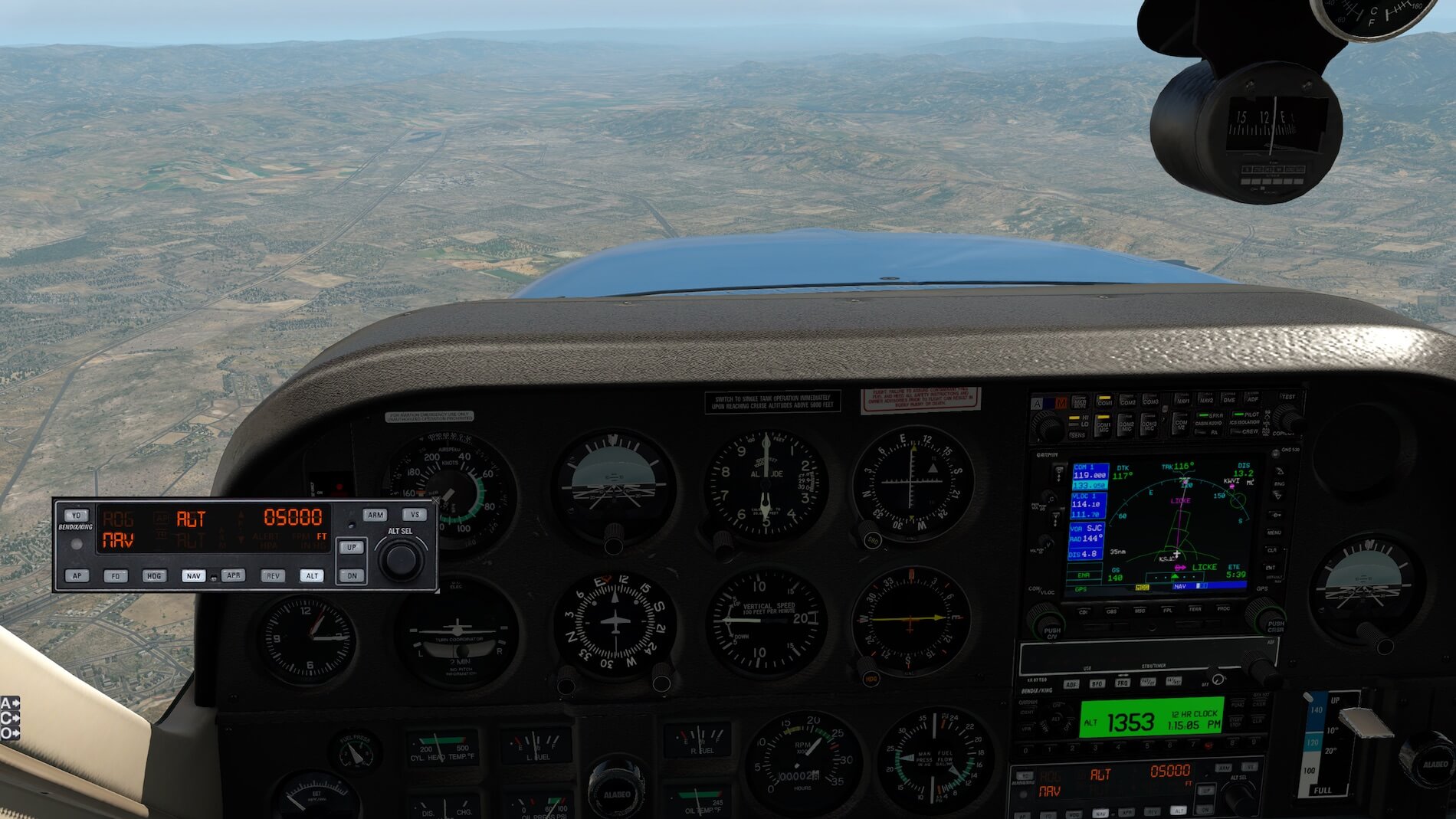
We ask for our clearance from Ground on 121.6 after indicating that we have current ATIS, and conveniently get “Cleared as filed. Climb to 2,000, expect 5,000 feet 10 minutes after departure. Contact NorCal Departures on 135.65, Squawk 1353”.
We read back the clearance correctly, set the transponder to ALT and 1535, set the heading bug to 120 (ATIS tells us that runway 12 is in use), and set our initial altitude of 2,000 feet into the auto-pilot altitude selector, then then ask for taxi instructions. We also tune our Nav 1 to the San Jose VOR (our first flight-plan waypoint), and center the CDI with a TO flag ( in X-Plane 11.26 the VOR won’t be received until airborne). We also set flaps 10 degrees.
We are told to taxi via taxiway Bravo to runway 12 and to inform Ground when we are ready for departure. We taxi to the run-up area, do our run-up checks, then contact Ground that we are ready for departure. They ask us to taxi to “Hold Short runway 12” and monitor tower as Ground gets our departure release from NorCal via landline. We switch comms to Tower on 119.0, and enter NorCal Departure into the standby comm. receiver on 133.95.
Meanwhile the tower is talking to NorCal for information on what initial heading to give to us and plan our departure with flow control. We hear Tower giving instructions to another VFR aircraft on down-wind to extend their base turn for an instrument departure and we know that they will be talking to us very soon (instrument flights always take precedence above VFR flights unless there is an emergency).
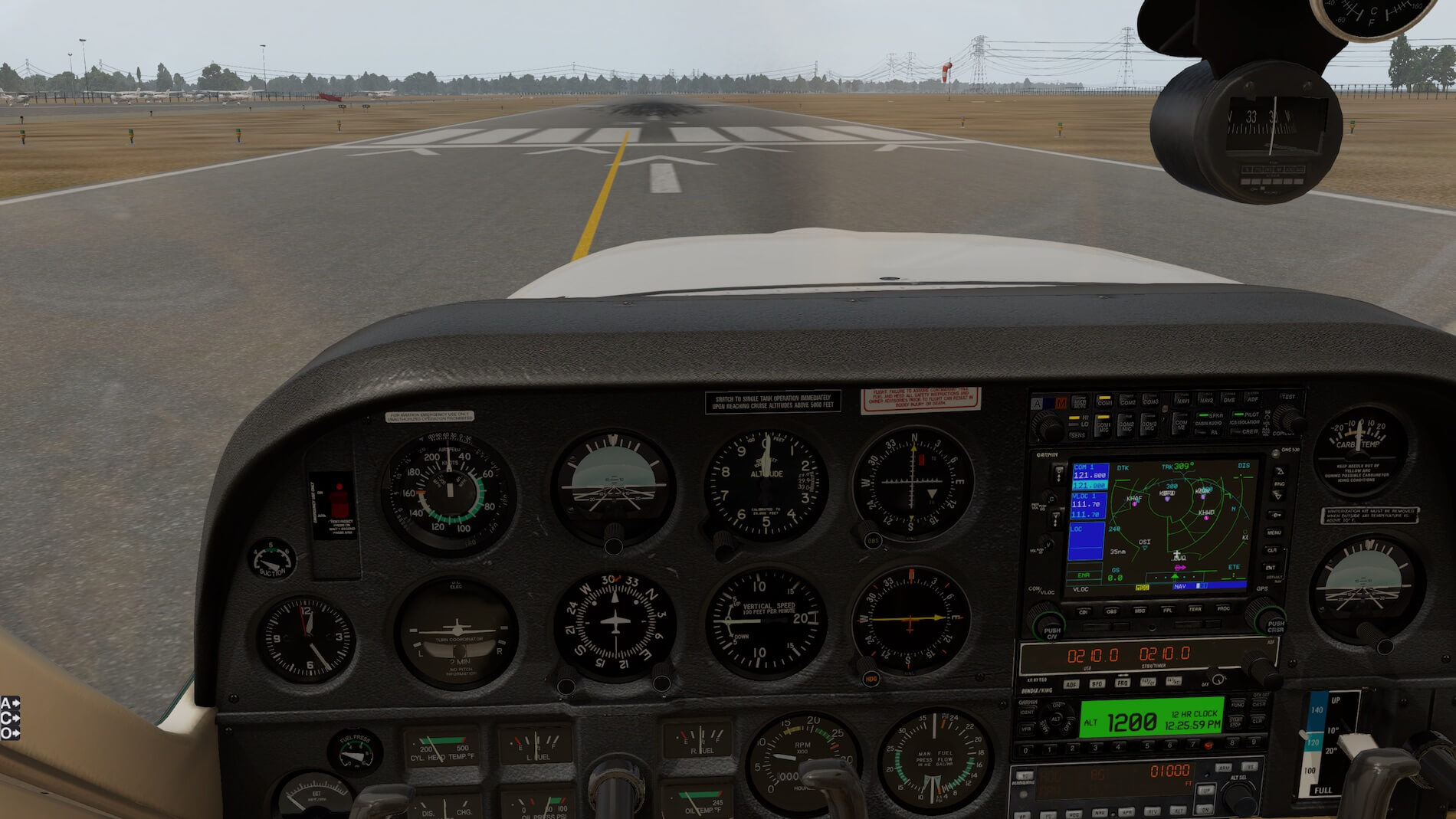
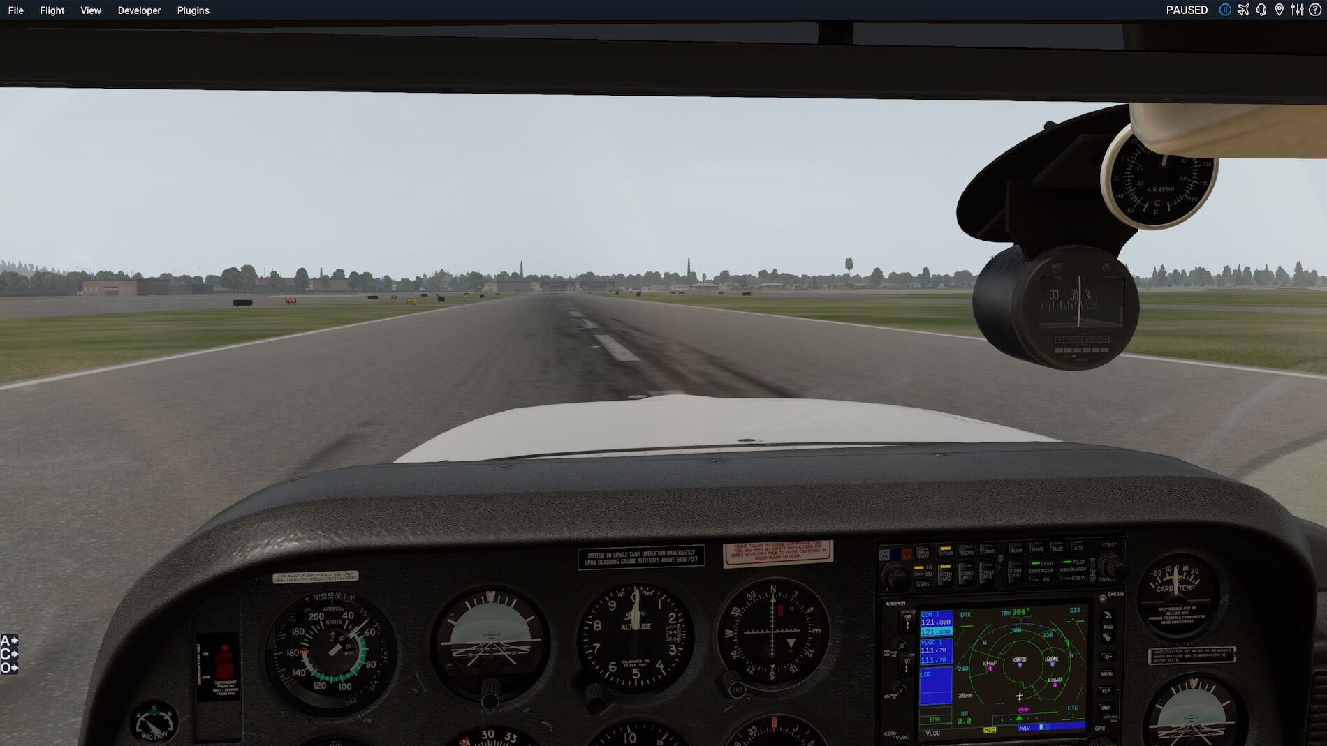
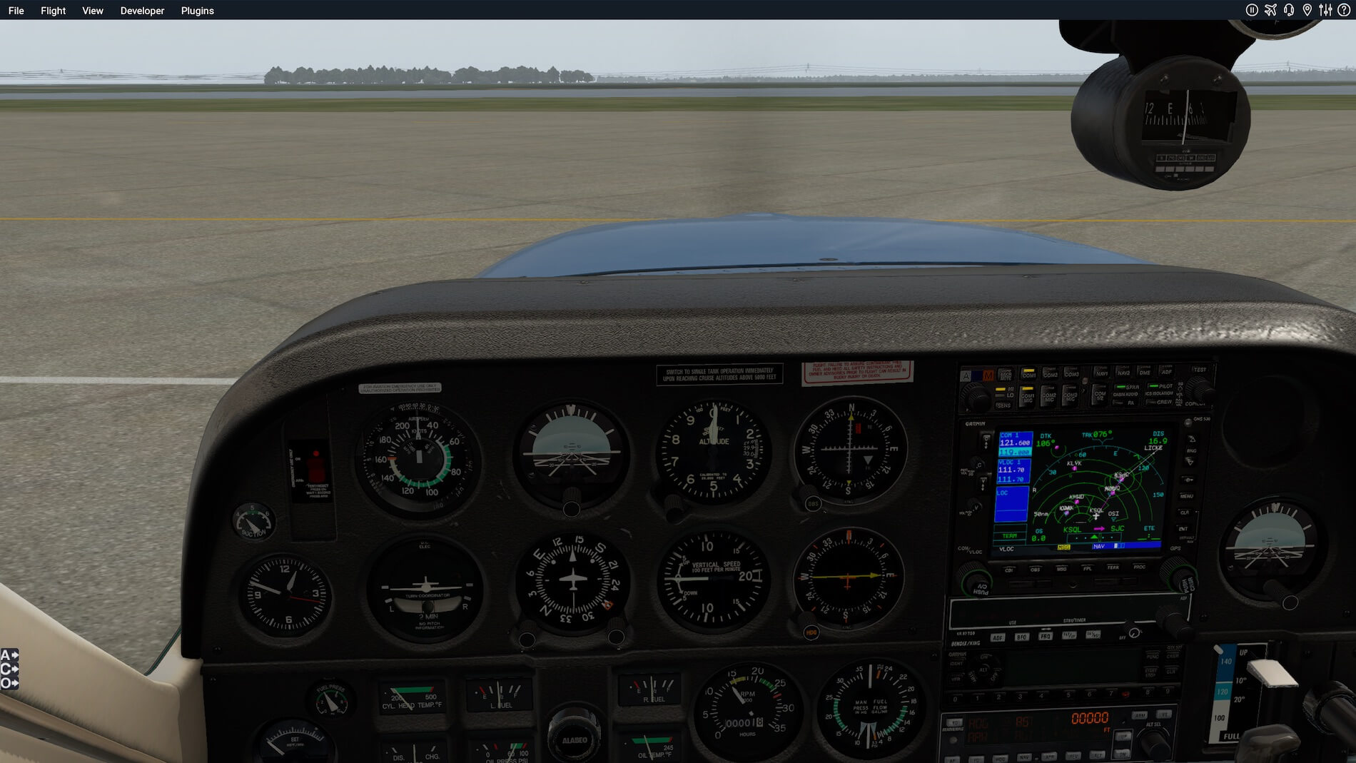
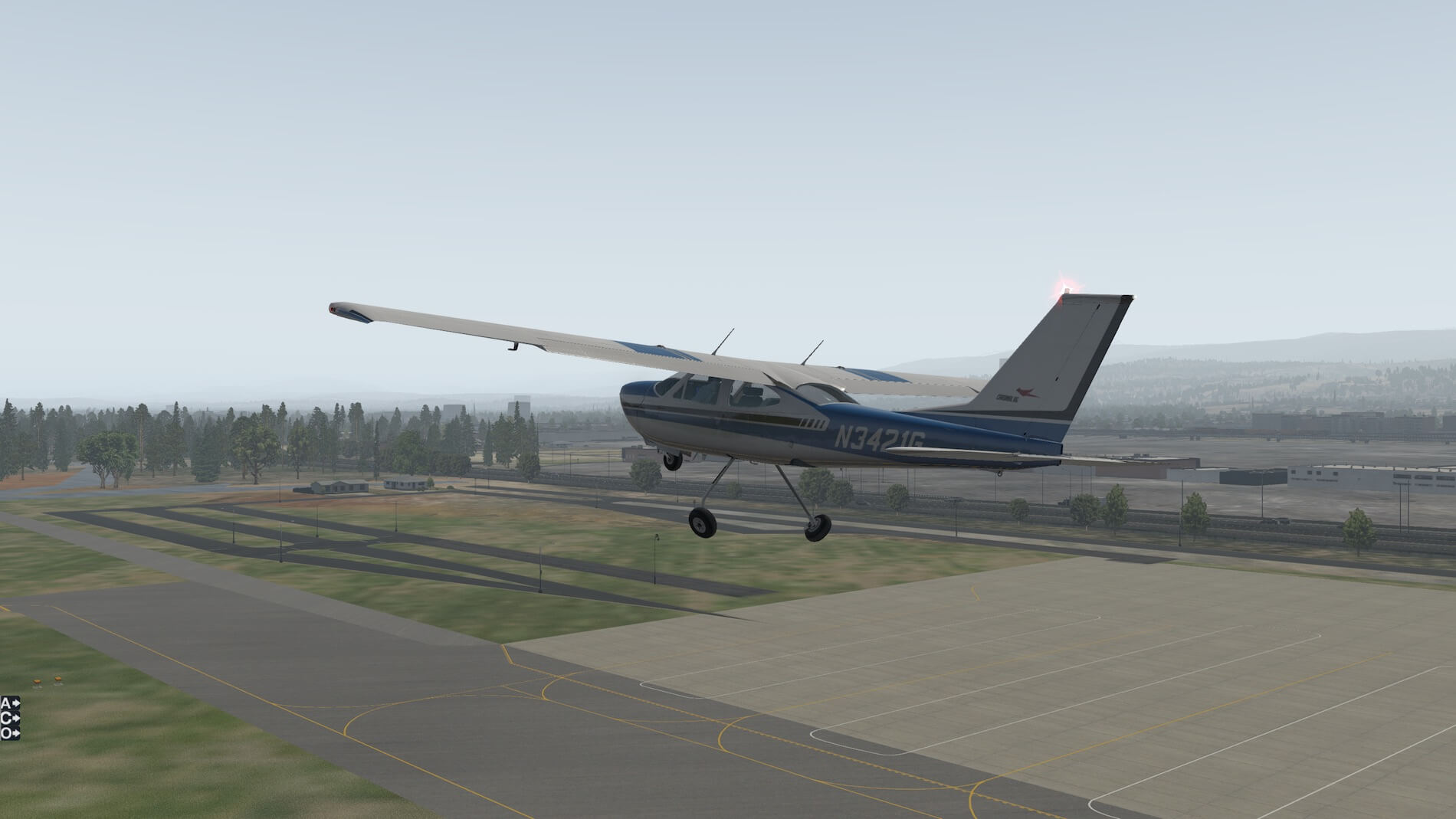
Tower calls and asks us to “Line up and wait, runway 12”. We do our final checks, turn our strobes and landing light on and hold on the center of runway 12 waiting for our departure instructions.

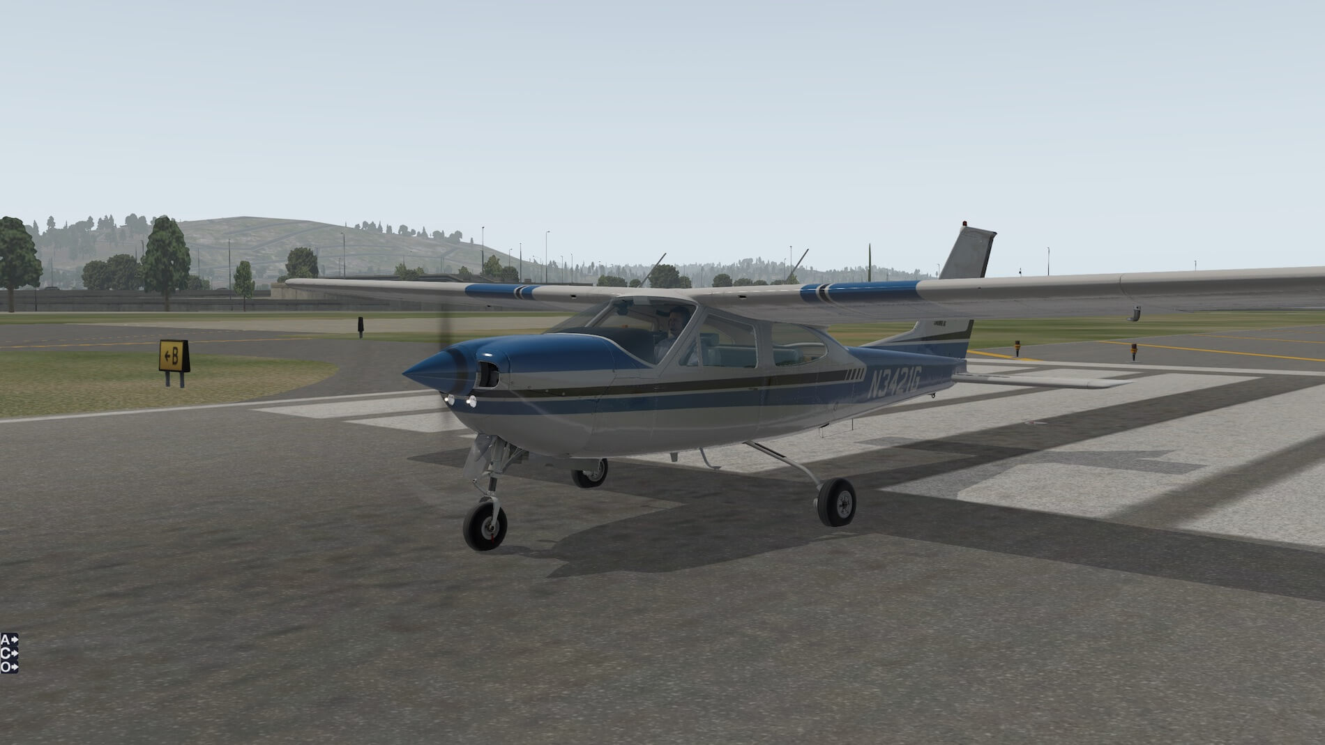
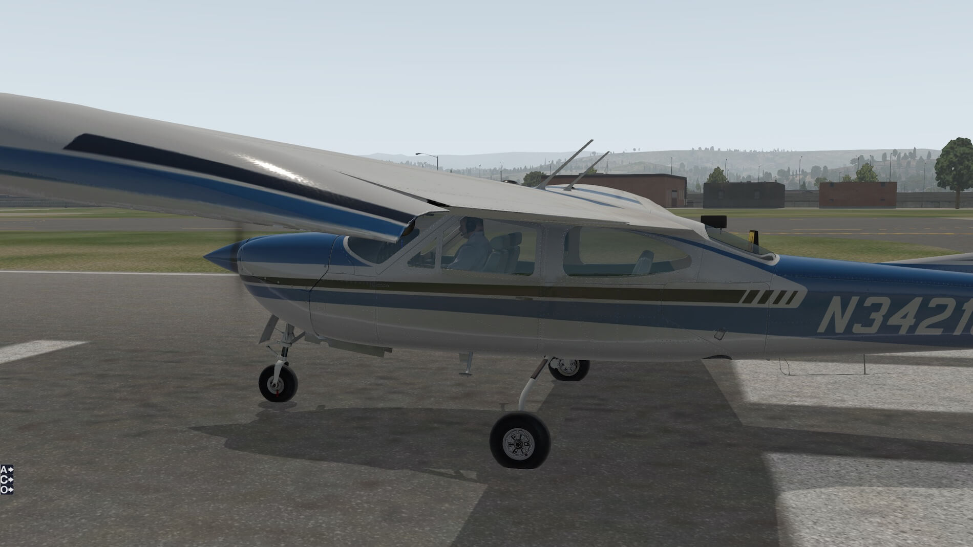
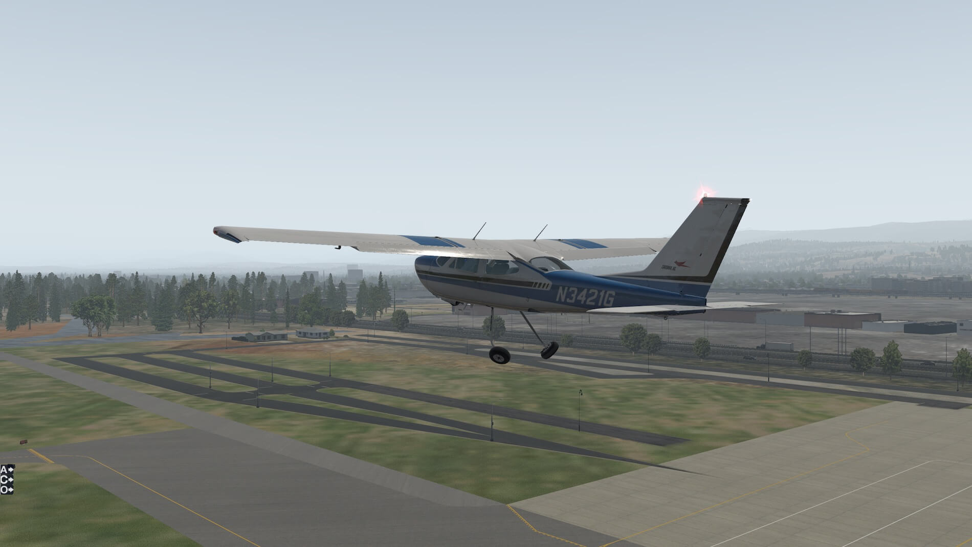
We are lined up on runway 12 awaiting departure instructions. The external view shows the smooth and sleek lines of this aircraft.
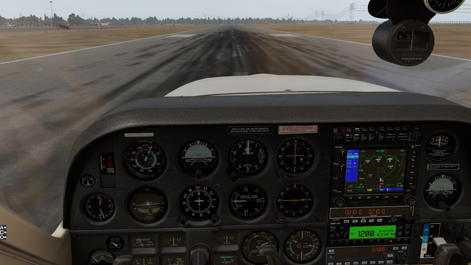
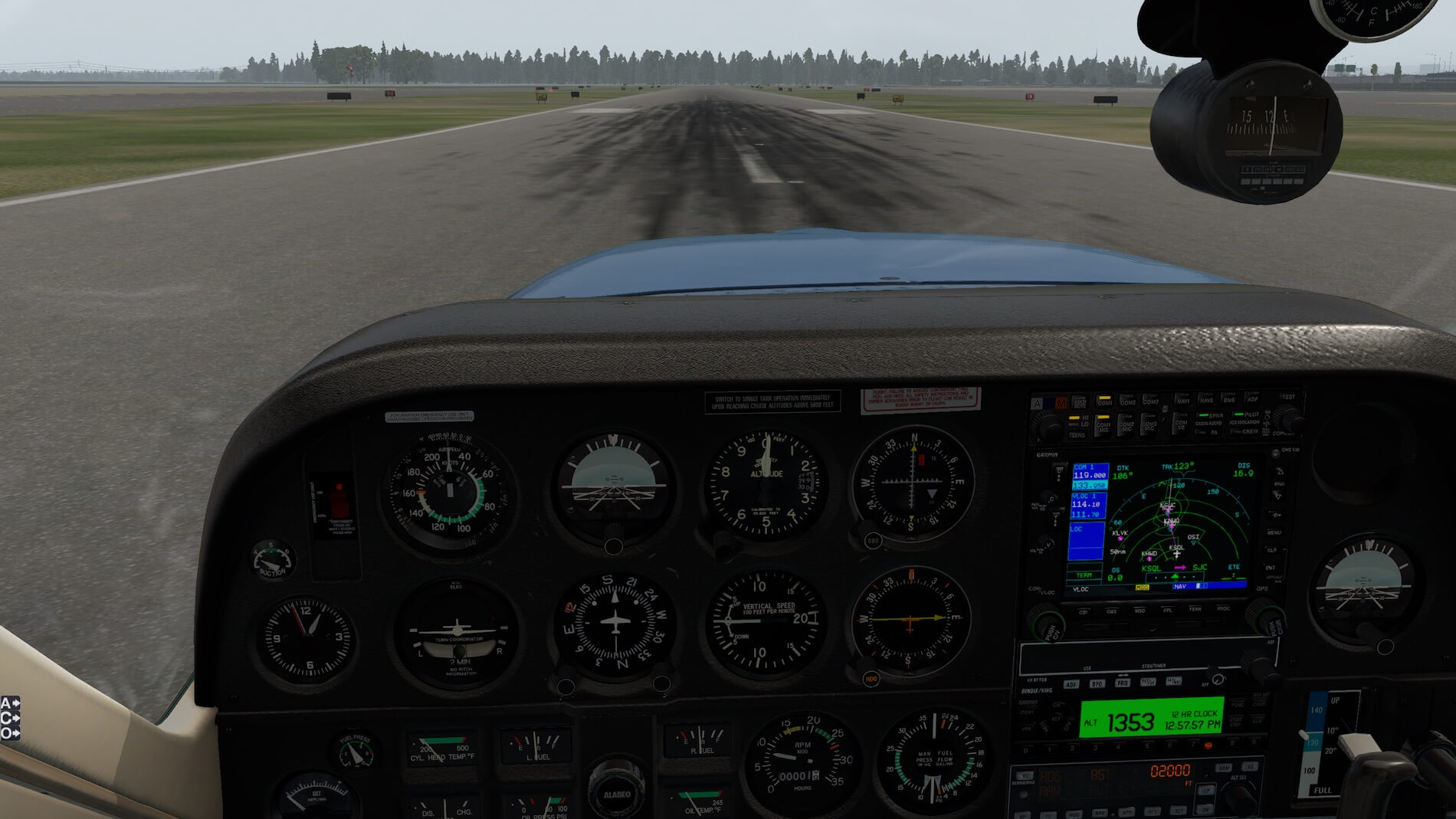
Tower clears us for departure and advises us to fly a heading of 100 after departure. Full throttle and we are off, we rotate at 55 KIAS, and when a positive climb rate is noted we retract the gear. Reaching 65 KIAS we retract the flaps. We need three conditions to be met prior to the turn to 100: a) Past the departure end of the runway; b) At least 400 feet AGL; and c) gear is retracted.
Tower is asking us to contact NorCal Departure, we confirm and set the comm frequency to NorCal departure, but we always fly the airplane first, so our radio work will need to wait until we get the aircraft stabilized in the climb. We now set climb power at a MP of 25”, and propeller RPM of 2500 (25 squared), reset the MP to 25” if required and set pitch with the yoke (not the trim) to 85 KIAS. We lean the mixture to 13 gph.
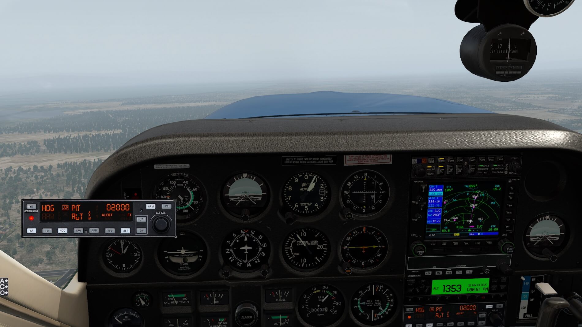
Flying IFR means being accurate in every aspect of flight. Since we have been cleared to 2,000 feet, and in this airplane that will occur quickly, we engage the autopilot. Press the “AP” button, which will maintain current pitch and bank attitudes. Select HDG, and ARM to arm the selected altitude.
Now the aircraft is flying a runway heading of 100 (as cleared) and still maintaining current pitch attitude. We can increase or decrease that by using the UP and DN buttons, or change the pitch attitude for climb rate by pressing the VS button. The vertical speed can be changed from what the autopilot captured when VS was pressed by moving the Altitude knob up or down, whereby the vertical speed changes in increments of =/- 100 feet.
For now we just leave the autopilot maintaining the current pitch altitude- and we need to watch the airspeed indicator to ensure that we haven’t set pitch too high (airspeed will drop if we had set pitch too high). The time interval since Tower told us to contact Departure until now is several seconds, at the most.
There’s a brief silence on the departure frequency and we contact them, giving our altitude and cleared altitude “….1,000 feet for 2,000..” We never know what they will give us in heading and altitude, so we listen very closely to the rapid stream of information.
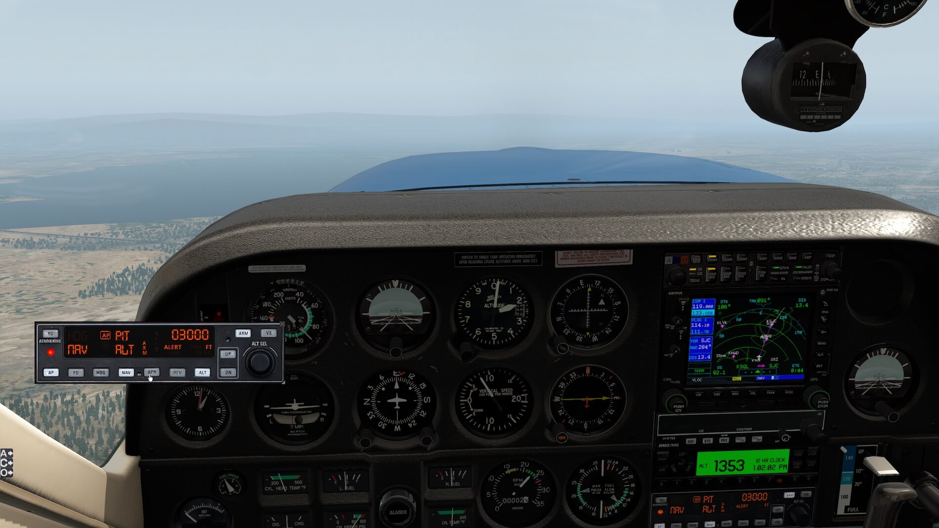
As would typically happen, there is no initial heading change, but an altitude change “Climb and maintain 3,000 feet, expect further in 2 minutes”. We now set the altitude knob on the autopilot to 3,000 feet, still monitoring airspeed- if everything goes well it should still be at 85 KIAS that we were trimmed for- however the autopilot is now using the trim to keep the attitude as we selected, so speed could have changed.
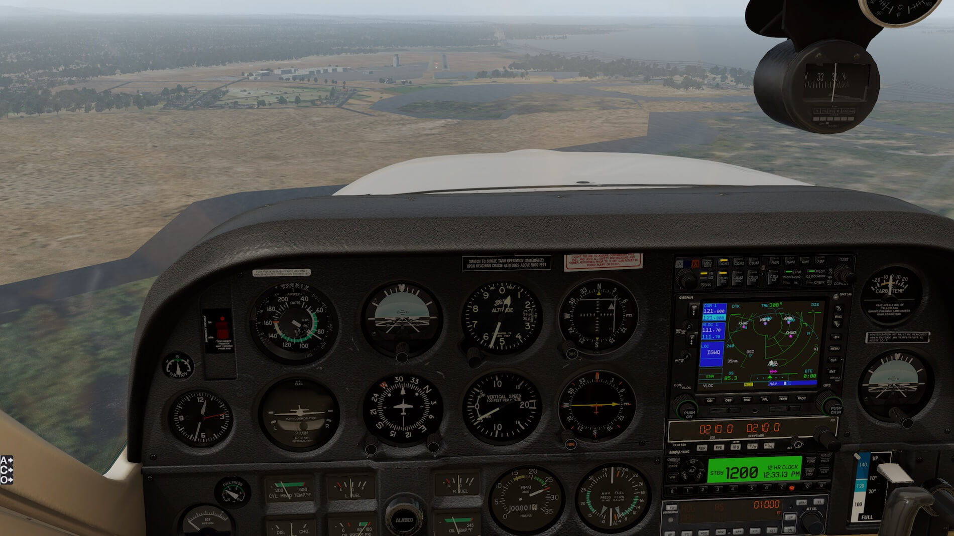
Departures calls us with “Fly direct to SJC”. We re-center the CDI, note the OBS heading and set our heading bug to that figure. Once we have attained the new heading, we set the NAV button on the autopilot (first making sure that the V/LOC is selected on the GPS navigator).
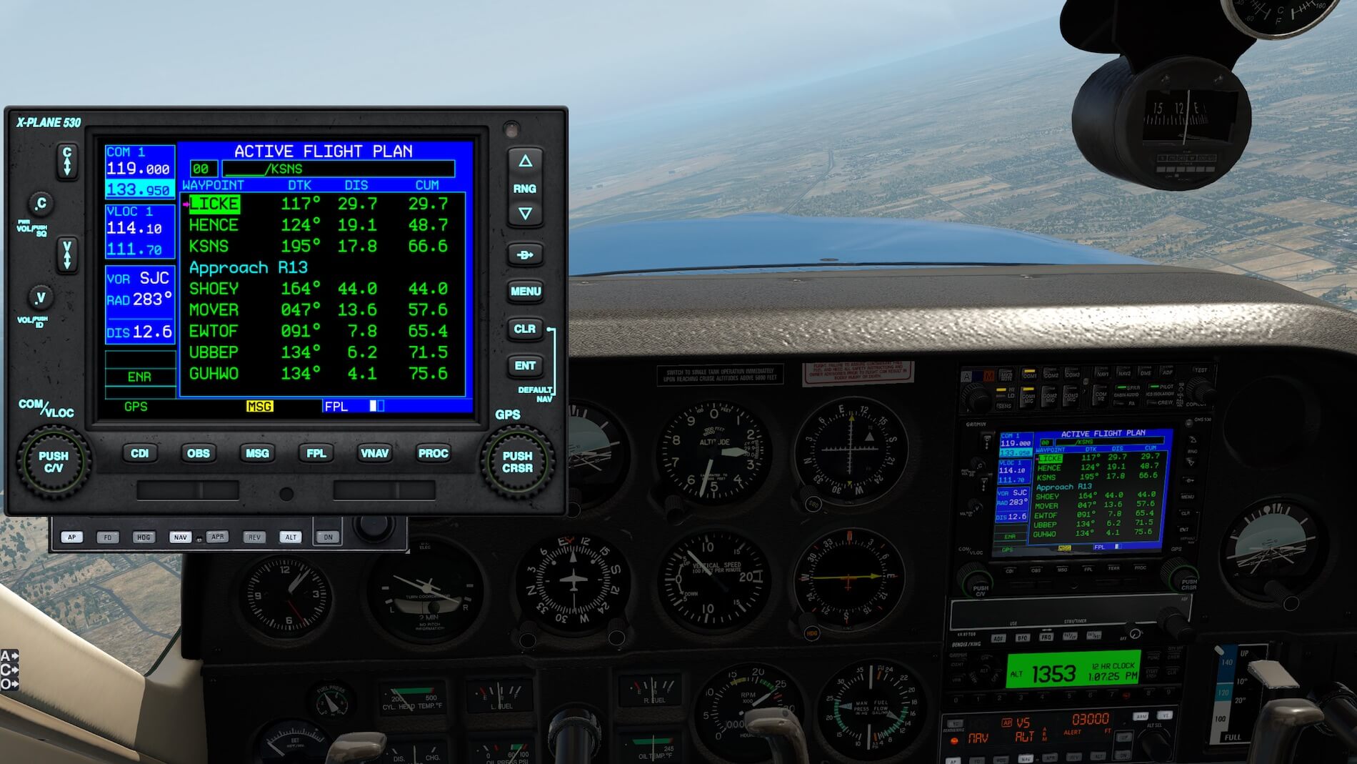
We are told to change frequency, we call the new controller with our current altitude, our cleared altitude, and “direct present position to SJC”. The new controller tells us to fly “….Direct LICKE, rest of route unchanged, climb and maintain 5,000 feet”. We select the Direct-to function on the GPS and select LICKE (it’s on our flight plan as an intermediate waypoint on V485), then select XXXX on the GPS. Now the GNS navigator is providing RNAV information to the NAV function on the autopilot. We bank to the right, and select 5,000 as our cleared altitude.
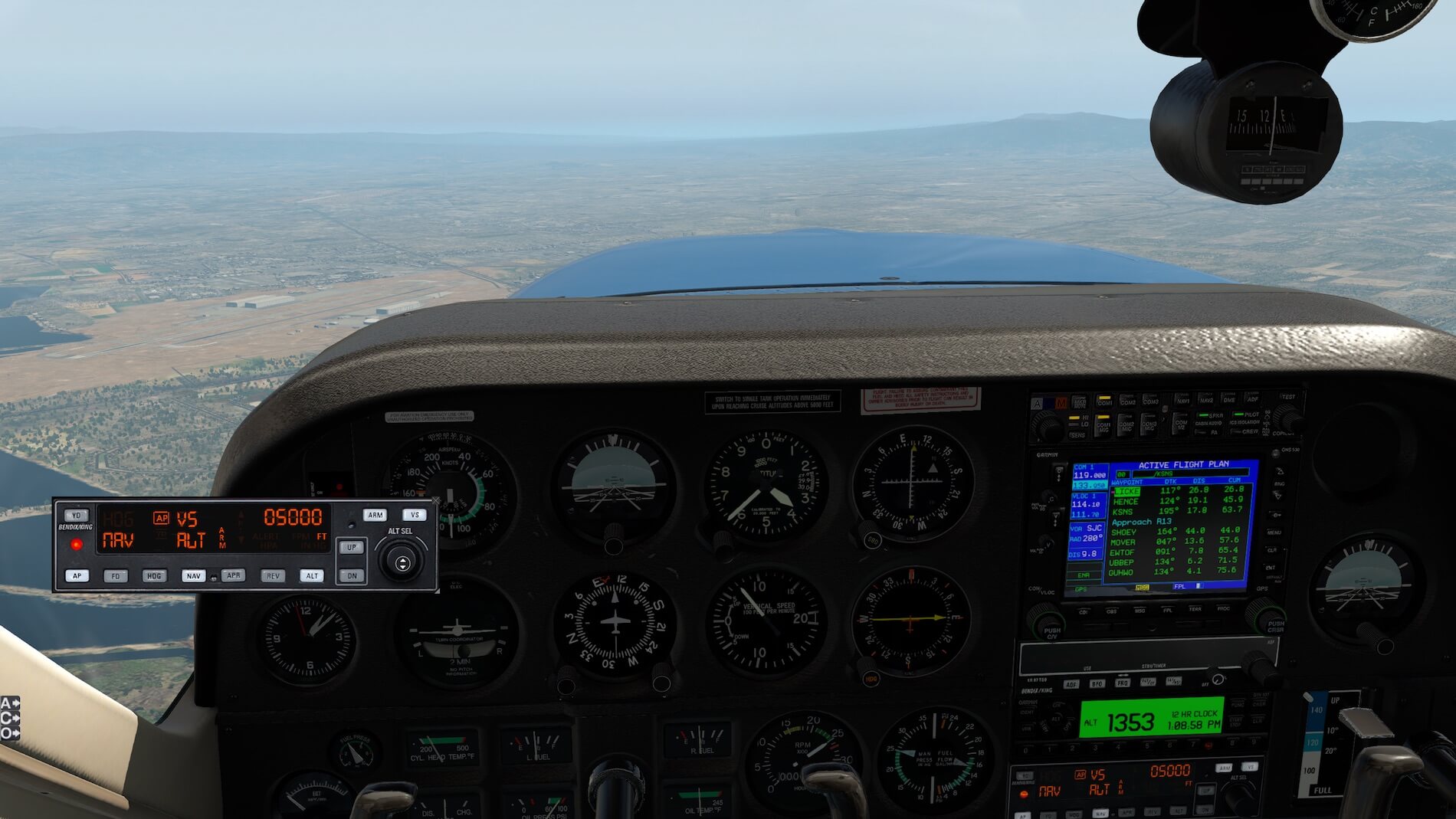
We decide to select the vertical speed option on the autopilot and note that it’s around 900 fpm, our current vertical speed. We reduce the VS by turning the Altitude knob counter-clockwise, back to 700 fpm, which lowers the nose and gives us better visibility.
Now we have captured the 5,000 feet altitude, and the autopilot has smoothly levelled off the aircraft. We now have to set up for cruise power.
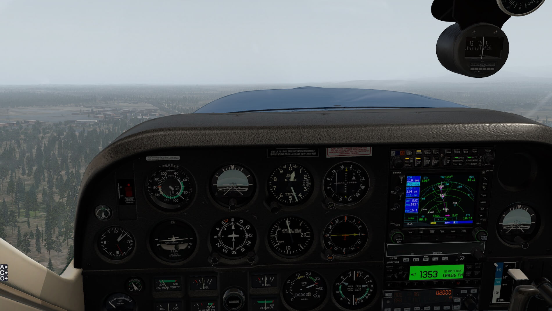
First we close the cowl flaps, throttle to 23” MP, Propeller RPM to 2300, and readjust the MP to the desired 23”. We also lean the mixture to 13 gph as per the Normal Procedures document, and readjust the MP to 23” if necessary. Once the aircraft has stabilized (as it does very nicely in a short period of time), we now need to check that our KTAS is in fact 140 KTAS.
There is no wind today so our KTAS is our ground speed, and IFR procedures call for reporting to ATC if our KTAS is off by 5 percent or 10 Knots (whichever is greater) from our filed flight plan. We can find the KTAS on our GNS navigator, but our airspeed indicator has KIAS, not KTAS. We know that (roughly) true airspeed increases above indicated airspeed at a rate of 2 percent for every 1,000 feet MSL.
Although this is a compound calculation, at low altitudes and airspeeds (as we are on this flight), a simple calculation can be used. We can simply deduct 10 percent from 140 Knots which should give us an approximation of 126 KIAS, it looks more like 130 KIAS in the sim- certainly close enough for instrument flying.
Stabilized in flight we now want to check how stable this flight model is. We disconnect the auto-pilot by pressing the AP button (we are now in control of the aircraft so we need to monitor closely our direction of flight and altitude).
The real thing will be more stable in the pitch attitude as it is in the bank attitude, something that the historical development of flight simulation has had difficulty in representing well. However- a credit to both X-Plane 11 in general and this flight model in particular, is that it does represent stability in a true and consistent manner. I really like this flight model! The rest of this instrument flight goes well with vectors to a visual approach at KSNS.


Summary and Conclusion
In full disclosure I have never flown a Cessna-177, however I do have significant time in a C-172 and have flown a C-182 with a CFI onboard. Both of these real aircraft are very stable and exhibit a heavy and stable feel, which is translated into the Cessna-177 very well. I am very impressed by the stability of the flight model, almost to the point that I feel it’s a shame to use the autopilot and let “George” have all the fun! When on an approach the aircraft keeps a stable rate of descent and speed, both of which are important for instrument flight.
From a visual perspective, the rearwards-placed cantilevered wing looks really nice and the windshield is certainly streamlined. The -RG model has a nice gear retraction sequence. I have always been more interested in flying the aircraft than considering what an external third person sees; however, the visual model is very well done with an attention to detail.
In order to show my full attention to this model I was reviewing I downloaded a new instance of X-Plane 11.26, without any add-ons other than updating with Navigraph data. Frame rates were good for my system at 40 fps on a 3-mile approach to KSFO 28R, which dropped to around 30 fps when on the runway (I believe the VFR haze in X-Plane 11 buffered the aircraft textures at 3 miles out).
For anyone who wants to step into the world of “complex aircraft” from a slower C-172 or similar, this product by Carenado is a beautiful way to do that. The aircraft itself has almost a “cult” following, due somewhat to its limited number of examples that were produced, and the uniqueness of the aircraft.
I would heartily recommend this X-Plane 11 model to everyone that wants to try something a little different, and in particular anyone who likes the world of general Aviation (GA) aircraft- where mostly flying is a hobby and a passion. I really enjoyed reviewing this model and had to use some self-discipline to stop flying and writing more and more.
The review is based on product version 1.1. For more information and buying details, visit the Carenado web page. The moment this Alabeo product becomes available via X-Plane.Org, we will add the link here too.
Feel free to contact me if you’ve got additional questions related to this impression. You can reach me via email Angelique.van.Campen@gmail.com or to Angelique@X-Plained.com.
With Greetings,
Bruce Knight
| Add-on: | Payware Alabeo Cessna C177 Skyhawk |
|---|---|
| Publisher | Developer: | X-Plane.Org | Aerosoft | Carenado |
| Description: | Realistic rendition of C177 Cardinal |
| Software Source / Size: | Download / Approximately 438MB (unzipped) |
| Reviewed by: | Bruce Knight |
| Published: | December 17th 2018 |
| Hardware specifications: | - iMac late 2017 - Intel i7 4.2 GHz - AMD Radeon Pro 580 8192 MB - 32GB 2400 MHz RAM |
| Software specifications: | - Mojave (10.14.5) - X-Plane 11.40 |
0 Comments