Part 2 – From Boarding to Landing and Flying
Introduction
Prior to the completion of this review, AFL released a version 1.2 update to the airplane. I have chosen not to alter my initial observations but I have added notes where additional testing of the update differed from my original notes so you can see what the update changed.
Also, AFL released an update to the KAWO scenery that added the AFL hangar that works with the key fob remote control included with the C172 NG.
A Look Inside and Starting it Up
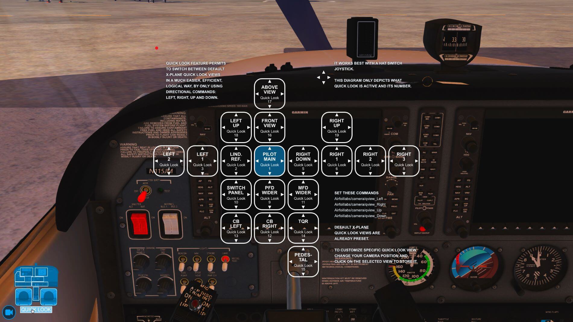
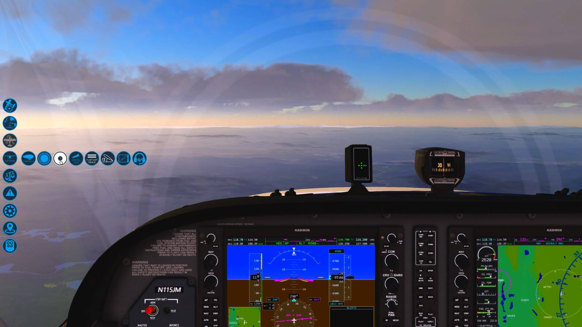
For a moment, before we continue the Preflight, let’s look at three menus you can activate when inside the cockpit. These menus pop up when you move your cursor to the bottom left of your screen or to the bottom right.
The bottom left has three options. If you click on any of the outlined sections of the instrument panel, the camera will zoom to that section. If you click on the camera below that, you will be taken to a sub-menu that will let you pick particular pre-defined viewpoints, and the camera will take you there immediately. Click on the camera again to return to the interior view options and click on the word Quicklook. This opens the schematic and instructions for Airfoil Labs quick look feature that lets you move through a series of views using only four commands.
They recommend using a hat switch for this purpose, but you can assign the commands listed to the right to any buttons or keys you choose. To change the view to something you want, activate the quick look with any of the assigned commands. When you get to the view you wish to alter, move the view to where you want it, bring up the quick look schematic and click on the highlighted active view. That assigns your current view to that position. This is a rather handy feature to have available and, with practice to adjust to it, it can be quite useful in your flights.


The bottom right pop-up is direct. It is another way to bring up the checklist. This can be useful when you need to keep your attention front and center but still need the checklist. Think emergency and you have an idea of when you might want to use it.
Complete the Preflight
Completing the outside portion of the preflight, open the pilot’s door if not already open, and click on the seat. This will place you back into the seat, from which we started the walk around mode, and ready for the Before Engine Start section of the checklist. Periodically, the checklist would not advance by clicking items with the mouse. In this case, I used the key stroke I assigned to the advance checklist function found under the Airfoillabs/Checklist section of the X-Plane keyboard option.
[Note: After the 1.2 update, the issue with clicking on the list remains and I again observed the checklist operating in semi-automatic mode when manual was selected. I had to flip the selection to semi-automatic and then back to manual for the manual operation to take effect.]
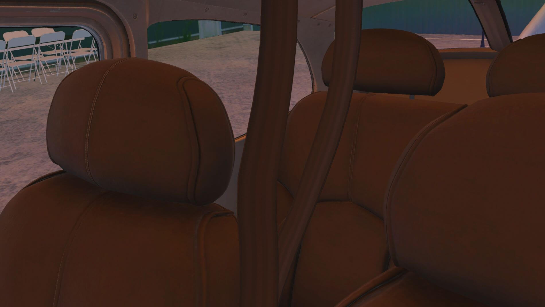
As the camera swings around for us to provide the passenger briefing, we see the texture work on the seats. The upper leather section is smooth and include detailed seams. If you look further down the seat, you’ll notice the change in texture indicating the use of perforated fabric. You can almost reach out and feal the canvas webbing of the seat belts that drape as realistically as any modeled belt can. The accurately textured roof features nicely modeled interior lights and switches.
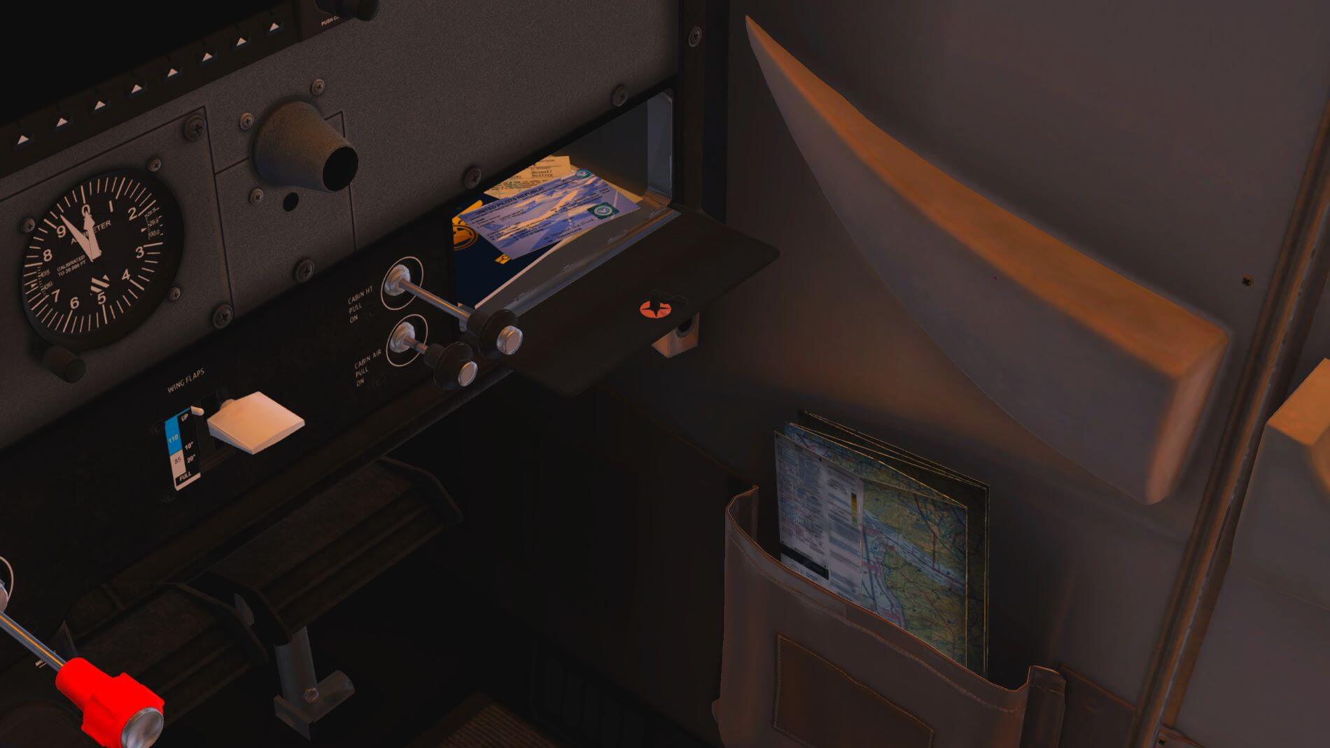
As we take this break from the list to look around the interior, we can hear sounds that someone sitting in the seat and moving around might make. One example of the detail included in this model. A couple of things I’d like to point out here that we haven’t yet looked at. One is the glove box. If you click on it, the ARROW documents pop up on your screen. You need to click on one of the documents to put them back in the box and click the lid to close it. Now, look down to the well modeled pocket on the co-pilot’s door. I almost expect the fabric to move when I click on the sectional chart to bring up X-Plane’s sectional map screen.
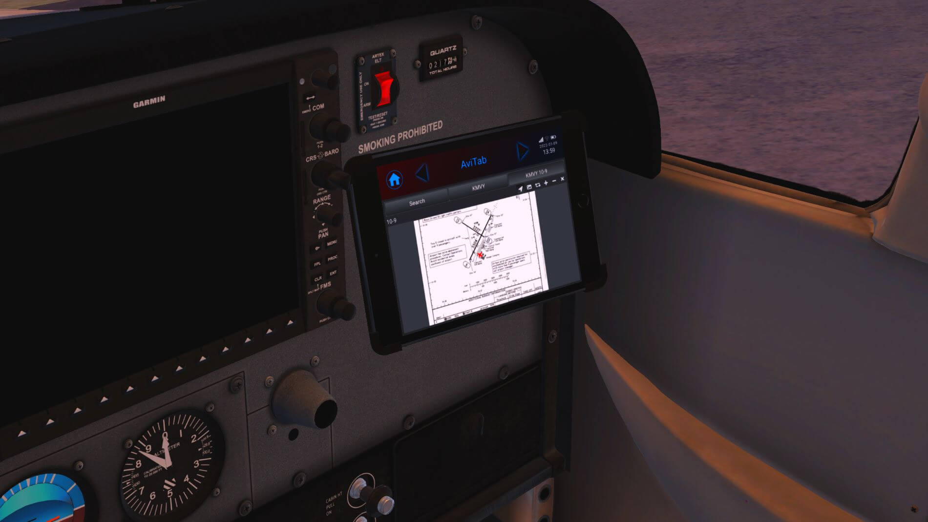
If you have the tablet option selected in the aircraft options list, you will see it above the glove box. You click on the power button to turn it on and off. You can click this general area to make the tablet appear or put it away. As you can see once you turn it on, AFL provides you access to many of the items from the main pop-up menu as well as to the AviTab, if you have that plug-in installed.
The tablet itself is skillfully crafted for appearance and functionality. It would be a huge plus if we could move it around a bit. Also, the banner with the forward and back arrows and home icon does not go away when selecting the AviTab, and that makes it very difficult to use the AviTab because the screen area is so small. By the way, if you’re thirsty, grab that drink cup by clicking on it and help yourself. A second click returns it to the holder.
Now that we’ve finished looking around, we return our attention to the checklist with checking the brakes being the next step. Be sure the parking brake is set. Most of the time, you will find it the way you left it. If you select cold and dark from the AFL menu, it will not be set, and the Skyhawk will lurch forward when you start it.
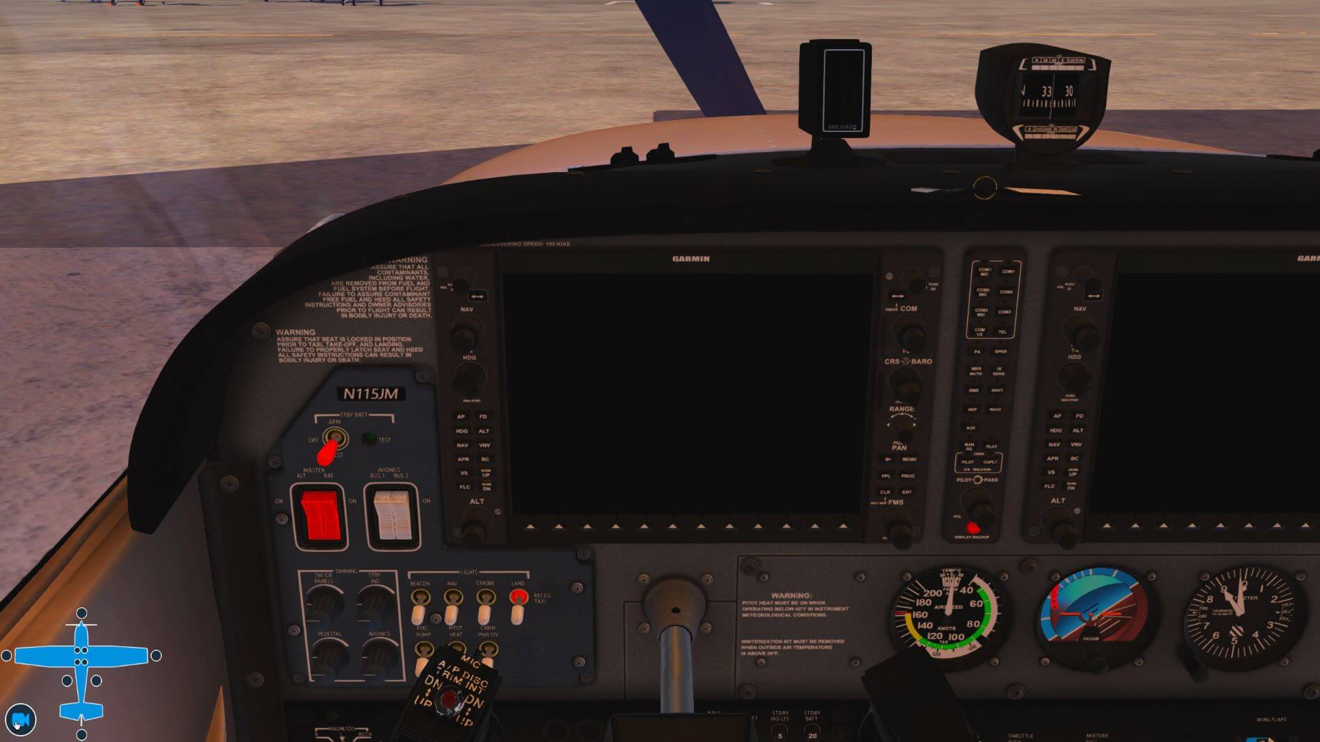
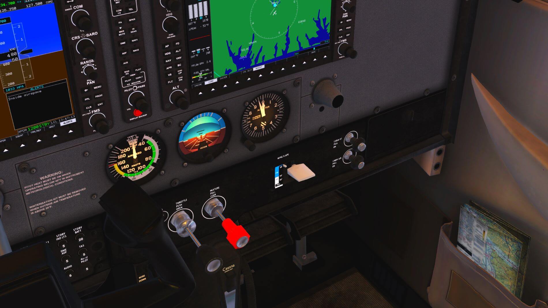
Next, we check all circuit breakers to make sure they are in. Airfoil Labs has rendered this panel quite well with sharp, clear, and legible text and detail right down to the screw heads used to hold the panel in place. Every one of these breakers is active and may, at any given time, pop out and cause some type of failure.
Ensuring all the breakers are in, the list then instructs us to make sure the avionics switches are both off. Note the caution regarding the state of the switches at start up. This is also true at shutdown. The purpose is to protect the avionics can from damage when the engine status changes.
[The implication was that you should just leave your radios on. Are you advocating that one not turn off the electronics before shutting down or starting up the engine? No . . I wouldn’t burden a battery with any unnecessary loads while it’s being horse-whipped by a starter. Everything should be OFF, including radios. HOWEVER, there are no special concerns to be observed for protecting a radio from perfectly NORMAL conditions on the aircraft power bus either. Check out this Aeroelectric PDF article.
Since I am flying with my CFI and the POH says to do it, I’m not going to debate the issue and I’m going to do it. Lastly is to make sure the fuel is ready by setting the selector valve on the pedestal to both (it should be on left or right from the last shutdown) and be sure the fuel shutoff valve is pushed in.
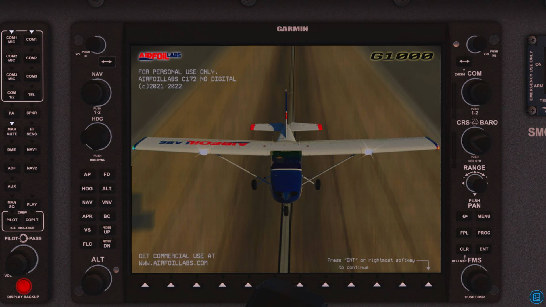
We are now finally going to start this thing. We are also going to get our first look at the customized G1000. Be sure to follow the starting procedure checklist in the exact order or this aircraft is unlikely to start. It can be a little tricky even when you do follow the list. This is one place where the pop-up engine diagram can be very useful. As a reminder, it is the last item in the second row [2D panels] of the pop-up menu on the left side of your screen. What we want to look at here is the priming gauge. The Airfoil Labs Cessna is very sensitive when it comes to priming and successful starting of the aircraft.
As an aside, I have noticed that the oil temperature, and the density altitude number on the right side of this window, do not seem to work properly. The oil temperature does not adjust realistically when temperature changes are set in the weather system. It is also always in disagreement with the oil temperature on the G1000.
Regarding the density altitude, I have yet to find that it agrees with my calculations [using the pressure altitude in feet + (120 x (OAT-ISA)) formula]. So, for the moment, consider these to be unreliable. I have not been able to figure out if this affects the flight model especially since it is difficult to measure distance in the sim. The oil temperature on the G1000 shows below the green range and requires several minutes at high RPMs to start slowly creeping upward. The oil temperature also drops quickly with a reduction of the RPM.
I have not seen this behavior in the default Cessna 172 with one of the accuracy-enhancing add-ins installed. [Release 1.2 addressed this problem. Oil temperatures are more realistic although the temp on the 2D panel does not match the G1000. Density Altitude is much more accurate although it still doesn’t exactly match the above formula results.]
Just a little something I learned about Preheating
It seems that pilots and mechanics advocate a pre-heat when the temperature is at or below 0° C. While the oil temperature is generally not the reason for the preheat since most modern oils are designed for use in a wide range of temperatures, it is the only indicator that gives us an idea of the engine temperature.
The real reason for preheating is the engine itself as Tom Ferguson describes in his article about preheating:
Almost all of the oil will drain out of the engine into the oil sump. A very thin coating of oil will remain on most parts, but by and large, all the oil ports and passages will drain. When the engine is started, it takes a few seconds for the pump to lift the oil out of the sump and distribute it throughout the engine. This is why it’s critical that you keep the RPMs near idle when starting. Often, I hear engines being revved up to 1500-2000 rpm during startup. I can’t help but picture the metal-on-metal grinding happening inside that engine! When the oil is cold, it’s even worse because the oil is thicker and doesn’t want to flow. When the oil is cold, it often takes 30 seconds or more for oil pressure to come up.
The engine shrinks as it cools. The colder the temperature, the more the engine shrinks. This wouldn’t be such a big deal if all the components were made from the same type metal. However, some parts are steel and some are aluminum. Even with the same temperature variations, aluminum shrinks and expands significantly more than steel. Moreover, aluminum absorbs and dissipates heat much faster; therefore, it expands and contracts at a much faster rate as well.
This can wreak havoc on the inside of an engine. For one thing, the steel crankshaft will shrink much less than the aluminum housings that support the crankshaft bearings. This greatly reduces the bearing clearances. In fact, in extreme cold temperatures these bearing clearances will be close to zero. On startup, with the bearings being dry and squeezed so tightly, they are subject to significant wear. Again, keep the RPM low on startup!
And it’s not just the engine that shrinks in low temperatures—EVERYTHING does! All the little gears, pointer shafts, and bellows in the instruments have a hard time moving; some electronic circuits don’t like the cold; radio nobs are difficult to move; engine controls can just lock up. Check out this Engine Pre-heat | Cessna Owner Organization link.
Not anything I would have thought of on my own since my car engine does not require it (it does not have the aluminum content a piston airplane engine has) and diesel engines need it because of the fuel viscosity, not the oil viscosity or the aluminum content of the engine).
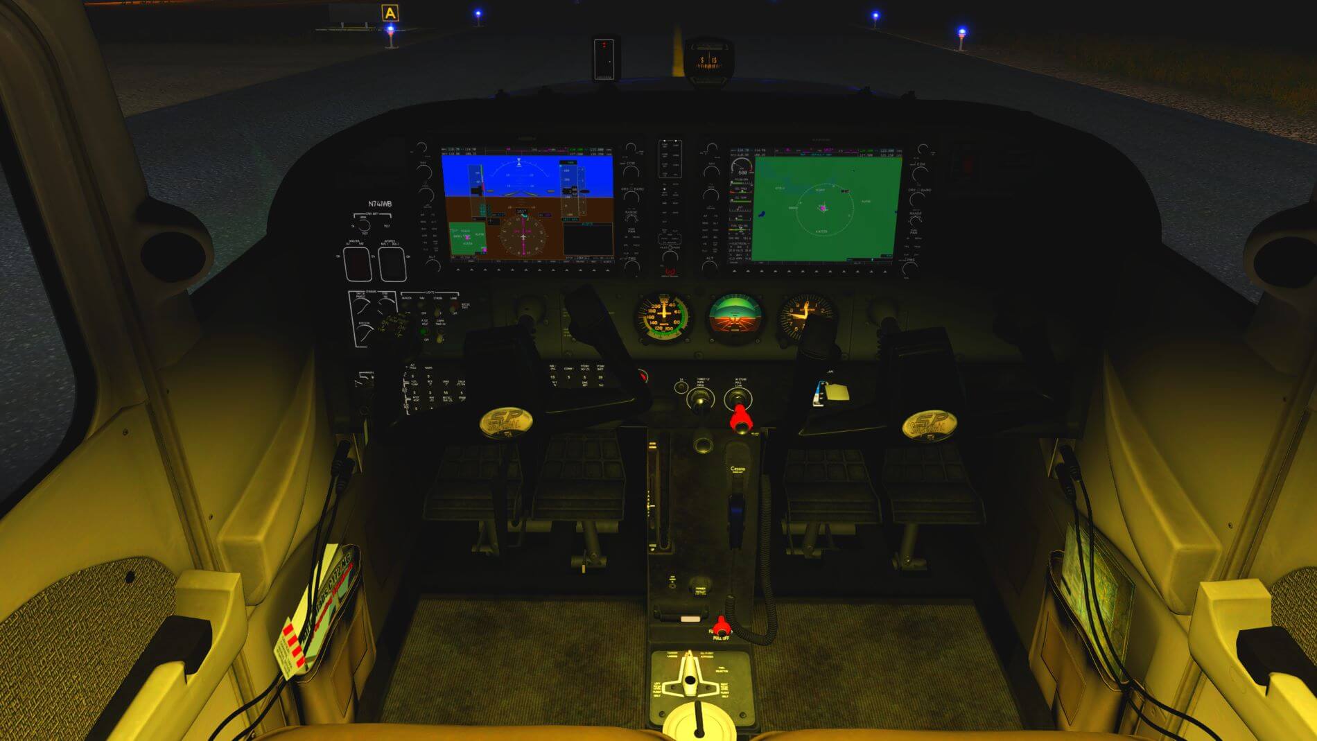
The G1000 PFD
Moving on in the list, we need to test the standby battery. We now get our first look at the customized G1000. The G1000 begins with an initialization that takes a moment to complete. It then greets us with a screen that has a bunch of red “x” marks through all the engine parameter indicators. We now wait for those to clear, and for the gauges to show us some actual information. These are the numbers that the list will ask you to check before moving on. A note here from the POH that Airfoil Labs did not include on the list: the Batt S amps indicator is supposed to show a negative value at this moment.
As you continue through the list, you’ll see the G1000 PFD display finish its startup and the familiar blue and brown background will appear. You can also see another customized feature next to the speed tape: various V speed indicators for this aircraft. VR is the rotation speed, Vx is the best angle of climb speed, VG is the best glide speed, and Vy is the best rate of climb speed. We will be checking these numbers when we take off.


Priming and Starting
We are now going to use the priming procedure since our engine is cold. Turn on the fuel pump and move the mixture lever to full rich and then back to idle cut off. Introduction of fuel to the engine only occurs when you move the mixture lever; the pump alone does not do this. The further you push in the mixture lever, the faster the fuel flows to the engine. The position you don’t want to spend much time in is the full rich position.
Do not do this too quickly or your engine will be under primed. Do it too slowly and it will be over primed. This is where the priming gauge on the 2D panel is almost essential until you get used to how quickly to move the mixture lever. Once you return the mixture lever to idle cutoff, you don’t have to rush to turn off the pump since it is no longer introducing fuel into the engine.
If you haven’t already, take the key from the glare shield and insert it into the ignition and move it through the magnetos settings to the start position. This is an automatic return so when you let go of the key, it snaps back to the “both” position and the starter stops. Hold the key at start until the engine catches. This can take a few seconds and may have you wondering if you primed correctly. When the engine catches, let go of the key and quickly but smoothly move the mixture to full rich.
The engine will stall if you do not move the mixture from idle cutoff with some urgency. I have found it necessary to assign a key stroke to the start command so I can release the key and move the condition lever simultaneously. If you still have the engine 2D panel open, you will see the cylinder automation and increases in each of temperature gauges.
The G1000 MFD
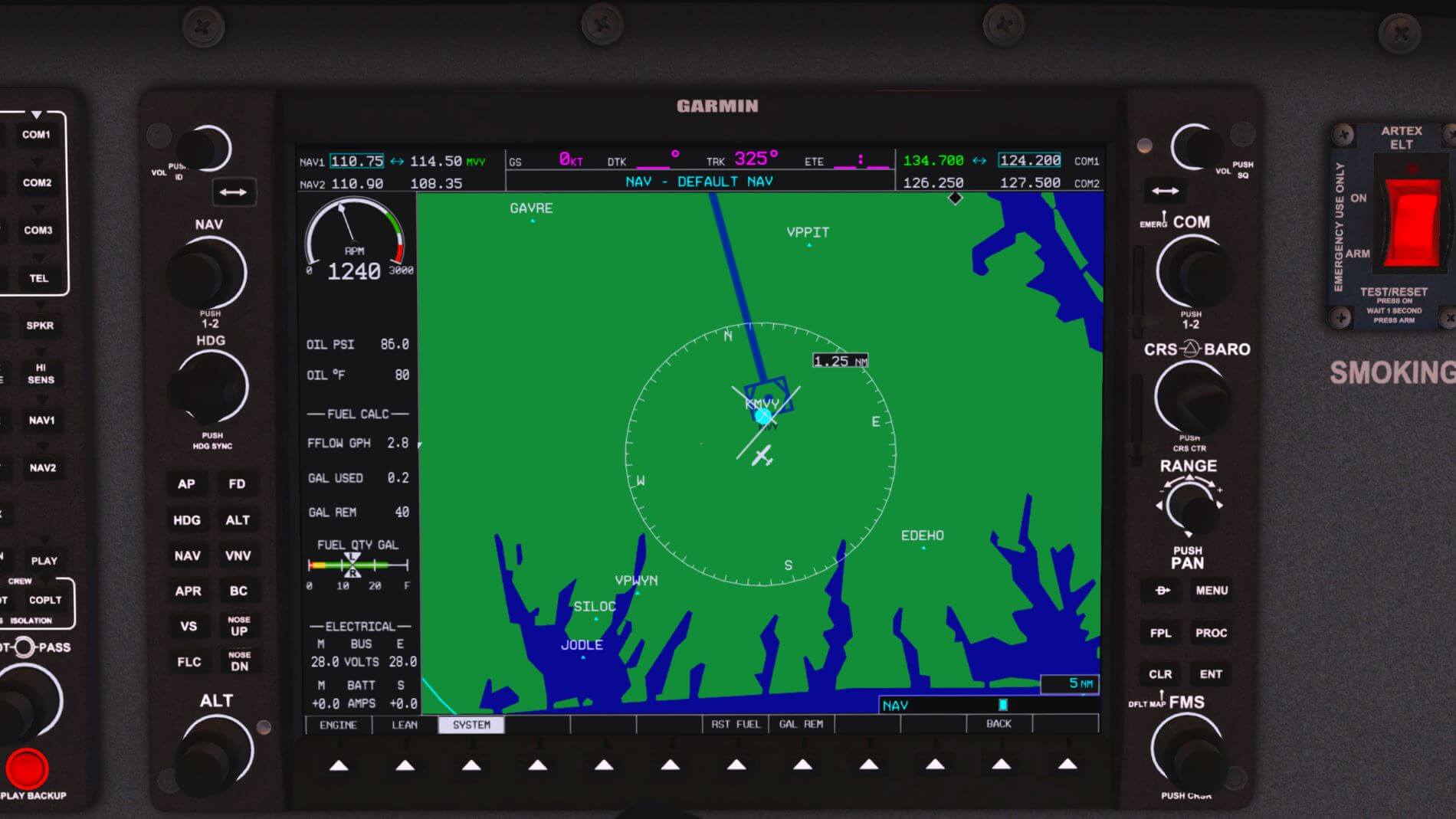
Continue the checklist to the end of the battery start. When you turn on the avionics, you will see the AFL custom screen on the MFD of the G1000. Click the indicated softkey or enter to move past the screen. We will now look at the added engine control panels that Airfoil Labs has added to the G1000.
Use the softkey to select the system option and it will take you to the panel that displays the oil pressure and temperature numerically. This panel also contains the fuel calculator and activates the soft keys for resetting the fuel quantities and adjusting the fuel remaining. Pressing the fuel remaining soft key activates additional soft keys that will allow you to incrementally adjust the amount of fuel to equal what you have on your weight and balance screen.
Leaning the Fuel
The AFL C172 G1000 provides two panels to assist the pilot with leaning the fuel. Given that this is a study level aircraft presumably for relatively new pilots, it would be nice if there was a pop-up explanation on what to do with this. Leaning fuel is not something that comes naturally to most folks since most other forms of motorized conveyances do not require it. Leaning is the process of changing the ratio of oxygen and fuel that is reaching the engine.
Proper leaning at cruise altitude produces optimal engine performance. Leaning before you taxi prevents the spark plugs from fouling with lead deposits.
Most important, a properly leaned engine yields the performance, range, and endurance figures found in the pilot’s operating handbook (POH). If you plan a flight based on those figures and don’t lean the mixture, you could run out of fuel. When you adjust the fuel/air mixture, you are decreasing fuel flow to the engine to compensate for decreased air density at higher altitudes. Less fuel is needed for proper engine operation as altitude is gained. Check out this AOPA Technique “Leaning the mixture” link.
Okay, that is what leaning is all about. Being a student pilot, I need to know how to do it and how do I use these screens to help me. Well, after a long and tedious search so I could present this information for you, I found it where one might expect – in the Cessna 172 POH, Section 4 under Amplified Normal Procedures.
You can find this online but make sure you get the POH for the 172S NAV III Avionics Option. The one I found dates from 20-Dec-2007. I do highly recommend getting a copy because it is helpful. The following is directly from the POH and will tell you how to use the G1000 Lean Assist page and the CYL Select function found when you click on the softkey marked LEAN on the MFD.
The cruise performance data in this POH is based on the recommended lean mixture setting determined from the maximum or peak EGT at power settings of 75 percentage MCP and lower. The 172S Nav III provides EGT indications for all (4) engine cylinders. The ability to monitor all cylinders is an aid in early identification and correction of fuel injection problems.
EGT is displayed on the EIS ENGINE and LEAN pages. The ENGINE page has a horizontal scale with a temperature indicator (inverted triangle) with a number representing the cylinder with the highest EGT. The EIS LEAN page provides vertical bar graph displays showing EGT for all cylinders. The cylinder with the highest EGT is shown in cyan (light blue). The numerical value for the highest EGT is located below the bar. The EGT and Cylinder Head Temperature (CHT) value for any cylinder may be shown by using the CYL SLCT softkey to select the desired cylinder. After a short period without CYL SLCT softkey activity, automatic indication of the highest EGT and CHT will start again.
To aid in leaning the mixture, push the ENGINE, LEAN and ASSIST softkeys, delta PEAK °F will display below the EGT °F numerical value. Lean the mixture by slowly turning the mixture control knob in the counterclockwise direction while monitoring EGTs. As EGTs increase, continue to lean the mixture until the hottest (cyan) cylinder reaches peak EGT. This is identified by the EGT bar graph for that cylinder changing to cyan with a hollow bar at the top. Note the delta PEAK °F and FFLOW GPH values for the first peaked cylinder. Peak EGT is represented by delta PEAK 0°F, if delta PEAK °F value is negative (-) the mixture can be on the lean side of peak. Enrichen the mixture by slowly turning the mixture control clockwise and monitor both fuel flow and EGTs until the leanest cylinder returns to peak EGT (delta PEAK 0°F) or desired setting based on the Exhaust Gas Temperature (EGT). Delta PEAK °F values rich of peak will also be a negative (-) value (-50°F). The lean assist system calculation is defined such that the peak EGT is the highest value and any lesser value is represented with a negative (-) value, whether on the lean or rich side of the peak.


So, there it is. Everything you wanted to know about leaning fuel in the 172. The last, and probably most important piece is the POH recommended lean is 50° and, for best economy, use PEAK EGT.
Climate Control
Airfoil Labs has created windows that feature several effects. The windows will show a color cast to them as the angle of the light that hits them changes. The amount of dirt on the windows is evident and may be problematic in some situations. Outside weather affects the windows. If you did not have the windows open while we were going through the interior survey and getting the engines started, you may very well be sitting in a cabin that has severely fogged windows.
If you fly through icing conditions, the windscreen will ice up and destroy visibility somewhat quickly. Flying through rain or sitting on the apron when it is raining or snowing, and wind is blowing, there will be visibility reducing streaks travelling up the windscreen and across the side windows. Rain and snow also produce individual drops on the windscreen. One interesting effect that climate control will not correct is the result of a bird strike.
While AFL did a remarkable job creating these incredibly life-like effects, the fogging can seem to come up quickly. If you aren’t on top of the commencement of icing on the windscreen, it will quickly become too built up for the climate controls to clear it. What you do to take care of these problems is use the two climate control knobs behind the co-pilot’s yoke along with the defrost vents on top of the glare shield.


Those black knobs up there do slide back and forth to open and close the vents. Now, in this model, the cabin heat and cabin air controls need to be full open to keep the windows clear. Use only one and nothing happens (no matter which one you use). Open them only part way and they fail to function. These controls are basically an all or nothing with the defrost vents being the only additional thing that helps keep the ice levels down. [Release 1.2 seems to allow fog clearing without having to have the heat on full. Cabin air remains a requirement.]
One last item that is sort of weather related. If you look overhead, you’ll see the sun shields. These do operate when you click on them and drag them to where you want them. They do cover the visual field and are, thereby, functional.
That’s it for climate control.
Flying The Cessna 172NG
How does one evaluate the accuracy of the flight model of a simulator aircraft when every model advertises it? Yet, three Cessna 172 models that I use each handle differently in identical situations. The Cessna 172 NG is now the fourth. In this case, I am going to try to find ways to evaluate AFL’s claims. Here is their list:
- Based on real aircraft flight recordings
- Performance tuned and correlated with performance tables
- Behavior details consulted with Pilots and Flight Instructors
- Additional custom behavior: Stall and Spin, Soft Field Takeoff, Crosswind Ground Operations
- Lift, Drag, Moment Forces Airfoils Data customized by internal plugin-based tweaker
- Detailed Damage Simulation as Bending of the wings, Overspeed Flutter, Flaps damage, etc.
- Wing Tail and Fuselage ground strike simulation.
- Flight Model is influenced by – Vortex Generators, Flap Gap Seals, Bush Wheels, Fairings, Broken Windshield, etc.
I have no way of knowing if the flight recordings are real so I am going to accept their word on that one as well as the performance tables although we can do a little checking on that. Consultations with pilots and flight instructors? Unless I can interview the folks they worked with, I’m going to have to take their word on that. We can attempt to evaluate the custom behaviors via comparison and noting differences in aircraft response to pilot input.
The detailed damage, ground strike simulations, and aircraft option effect on flight model are easy enough to test.
In Part 1, I listed specifications from the Cessna Flyers Association. Those specs differ from what is in the POH so it will be interesting to see which set we come closer to. The POH specs are:
- Maximum at Sea Level: 126 kts.
- Cruise, 75% power at 8500 feet: 124
- Ceiling: 14,000 ft.
- Take Off: ground roll 960 feet
- Landing: ground roll 575 feet
- Stall speed power idle: Flaps up 53 KCAS
- Flaps full 48 KCAS
Well, let’s begin and see what we can come up with. For any tests other than specific crosswind tests, the parameters used were those noted in the POH. Weather conditions were set for a standard day: 15° C with atmospheric pressure at 1013 HPa at sea level. The Cessna carried fuel and payload to amount to 2550 pounds take-off weight and equipped with fairings per the note in the POH. I conducted the flights off Runway 14 at Boston’s Logan Airport at an elevation of 20 ft. ASL. There was no wind.
General Handling
Taxiing from the apron to the runway is pretty much as I’ve come to expect in X-Plane. Ground handling is a little touchy. Taxiing with RPM’s above 900-950 rpm resulted in a rapid increase in speed that increased the work needed to maintain the craft in a relatively straight line. It took a substantially longer distance to slow to a speed where the brakes could be comfortably applied without inducing a nose drop and wear on the front strut.
Use care when braking to assure an even application of both toe brakes; otherwise, the Cessna will very easily squirrel off to either side. Once loss of control occurs, a bit of effort is required to get it back. [Initial tests with the 1.2 update show this to be more comparable to the default Cessna than it was.]
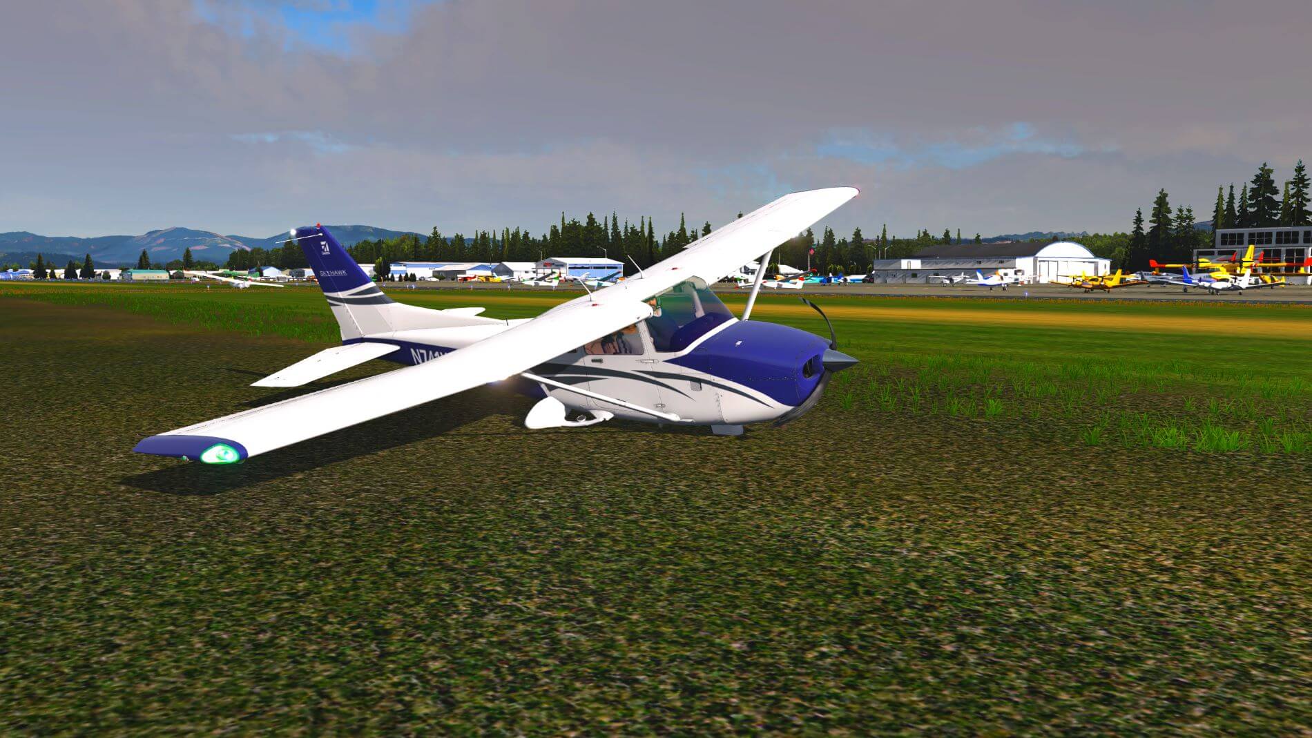
It is advisable to land at published speeds. Not doing so easily results in floating down the runway or touching down at too great a speed. If the landing speed is too fast (over 65 kts. in my testing), it is very hard to apply the brakes evenly. Landing in a crosswind requires crabbing techniques and lining up on the runway with ailerons in an appropriate configuration. In some cases, I had to land at a higher velocity with no flaps to remain anywhere near the centerline.
Changing to the bush tires does make a difference for ground handling as well as taxiing, take-offs, and landings
I don’t think any of the ground handling observations are out of line with what Airfoil Labs would have us expect. The crosswind behavior of this aircraft is different from that of the default 172.
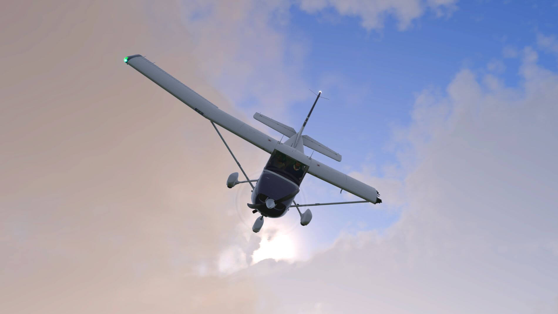
In the air, the Cessna consistently demonstrated an unsteady roll axis with a desire to drop the left wing on ascents and drop the right wing on descents. As much as I tried to trim for a steady pitch the plane struggled to maintain it, even in the no wind conditions. It has what I would consider an exaggerated tendency to drop the nose, gain velocity and increase lift, then nose up and quickly repeat the process.
Any small aircraft that is “well-behaved”, as Langewiesche would call it, is supposed to demonstrate this tendency but I was able to achieve more stability when trimming the default Cessna. Additionally, the aircraft consistently felt very light, floating on the slightest wind and crabbing on a 1-2 mph crosswind. This differed a bit from the default Cessna with an add-in. As with my other observations, it will take someone else to determine if this is accurate behavior. [As of version 1.2 released 1/12/2022, the pitch tendency has stabilized quite a bit. AFL lists two elevator issues in the release notes for this update.]
It is essential to keep to specified airspeeds when using flaps. The flap actuator will damage very quickly if you do not and that will end your ability to adjust the flaps until you repair it.
The airplane responds vigorously to turbulence and soon becomes near uncontrollable in as little as moderate turbulence. This coupled with the innate pitch instability makes this Cessna virtually unflyable in reported turbulence. [This has demonstrated improvement with the 1.2 release].
By the Numbers
I repeated these scenarios multiple times over several days to arrive at what I am writing here. Your experience, should you decide to try this model, may certainly vary. I did not have any performance changing plug-ins installed and, again, weather was set as a standard day at sea level.
Smooth take off rolls: consistently started in the 55kt. vicinity. I was able to start as early as 39kt. but it was not smooth, and the stall warning alarm was protesting the move. Upon landing, the lift seemed to drop off right in the vicinity of the published stall speeds both with and without flaps. I made this observation by floating over the runway about 10 feet off the ground and noting the speed at which the plane dropped (with a bit of a thump) to the asphalt. I did not perform a flare for this observation.
Stall speeds: in the air were pretty much by the numbers. I was able to maintain lift a little lower than the published number, but this was not consistent. As mentioned earlier, the stall speeds over the runway were pretty much spot-on.
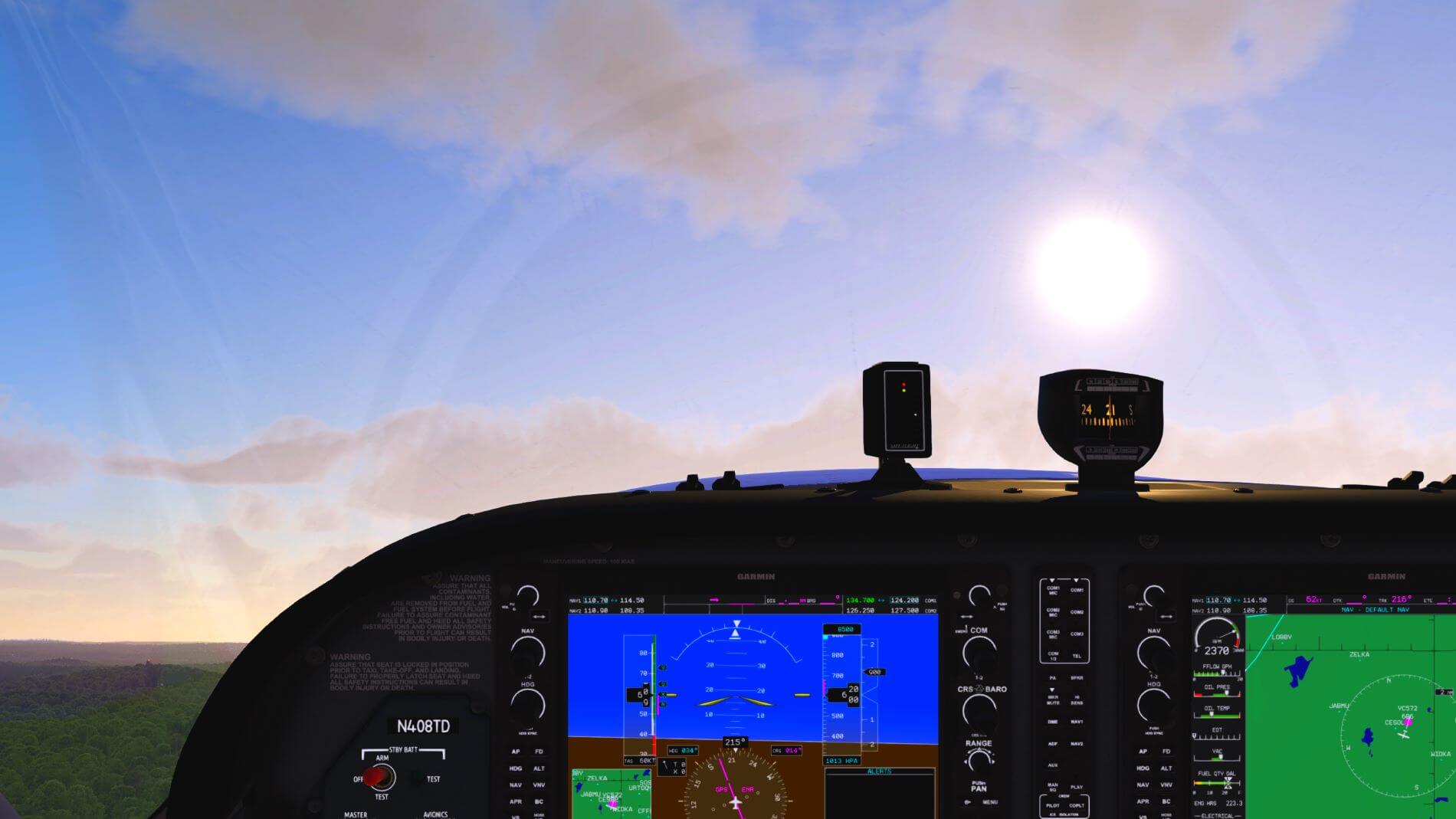
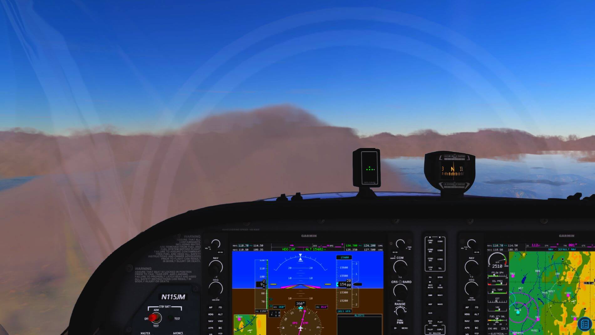
Rates of Climb: This was a tough one due to the pitching tendency of the aircraft. By the time I could get the plane at the appropriate V speed, I was frequently over one-thousand feet. It was difficult to maintain the speed long enough for the vertical climb rate to stabilize at a reliably measurable number. The two screen shots below will, for the most part, tell the story of demonstrated rate of climb consistently being higher than the published table in the POH.
I conducted these tests at full throttle and full rich mixture below three-thousand feet. The POH instructs the pilot to lean for highest RPM over three-thousand feet. While my climb rates varied from 700 fpm to 1200 fpm, they often settled between 800 and 950 fpm below 2000 ft ASL. [As of the version 1.2 update, AFL has greatly improved the pitch instability. The aircraft continues to demonstrate left to right swaying behavior when trying to maintain Vx and is much more noticeable when the AP is in use.]
Maximum Speed: of 126 kts at sea level is very attainable. On occasion, it is possible to exceed the speed. This appeared to be a result of the aircraft sometimes allowing me to lean for 2700 RPM at sea level which is inconsistent.
Cruising Speed: of 124 kts at 8000 feet using 75% power could not be replicated. The only time I could get near this was when I managed to redline the RPM at 2710. I was not able to do any better with the default Cessna. Both aircraft demonstrated a maximum speed of +/- 115 kts on the speed tape (Indicated airspeed).
Ceiling: On my perfect day, the 172 finally gave it up at 15,400 feet.


Aircraft Options
Airfoil Labs states that the options available for the exterior of the plane affect the flight model. Cessna’s footnote on the performance charts states the indicated speed numbers are achieved with the fairings on which reduces the range numbers.
For the following, I set my cruise speed for 115 kts at 2660 RPM with regular tires and fairings and installed the flap gap seals. Auto pilot maintained the altitude at 8500 feet, and I did not adjust the throttle when making changes. I added each item, removed it, and waited for the initial speed to recover before making the next change.
Removing the fairings dropped me to 113 kts at 2460 RPM. Changing from the regular tires to the bush tires dropped my speed to 110 kts at 2620 RPM.
The vortex generators reduced my speed to 111 kts at 2630 RPM. I did not notice a difference in the handling of the aircraft with them installed. I do not know if the integration of this part with the aircraft is different, since the ones attached to the rudder remain in place when the rudder moves.
When I removed the flap gap seals from my base configuration, my speed dropped to 112 kts. at 2640 RPM.
These variations certainly support AFL’s statement that these items affect the flight model. I was unable to discern any change in the handling of the craft apart from the speed reductions. The only other significant difference, as previously mentioned, is the alteration in ground handling caused by using the bush tires.


Scenarios and the Failure Window
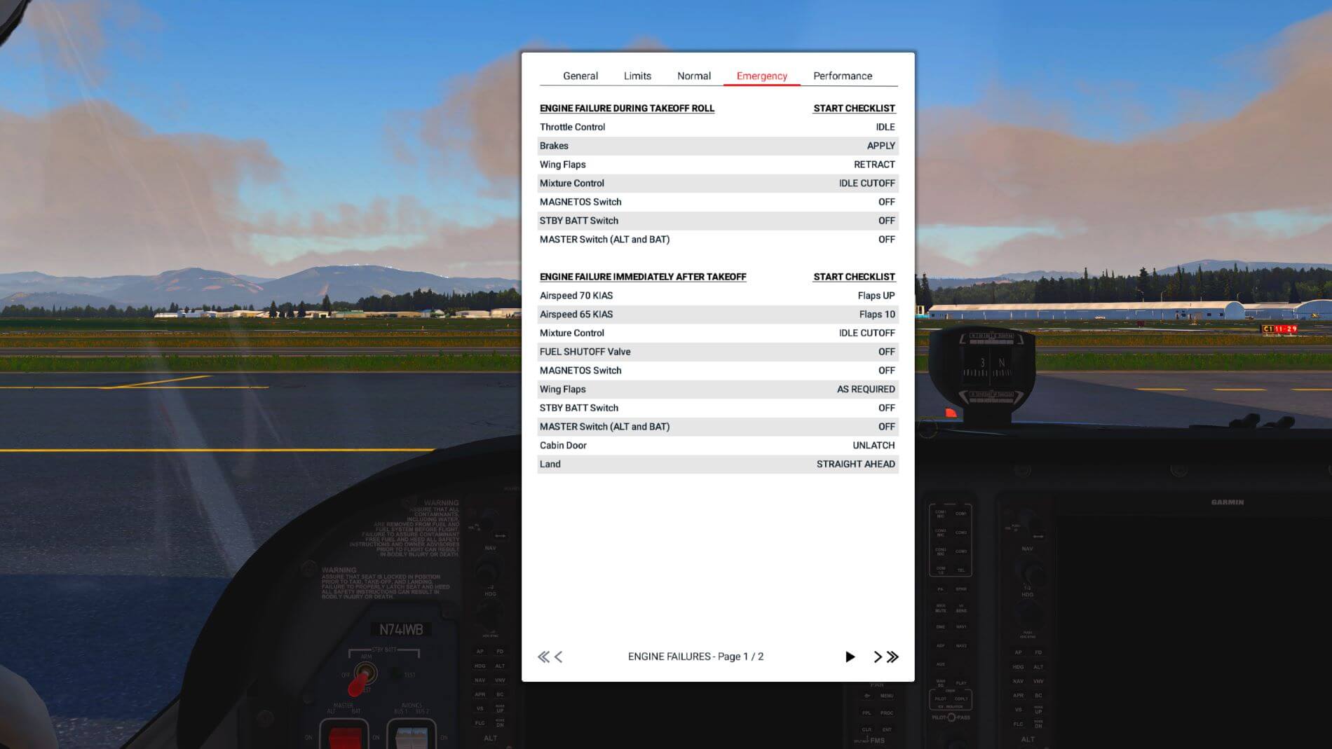
So, we finally got this thing into the air and put it through some of its paces. Now, let’s look at what makes this model of the venerable C172 a bit more challenging to fly if a challenge is what you are looking for. These scenarios can also be a good way to become more familiar with the emergency procedures checklist.
The emergency procedures checklist is an interactive list as is the normal checklist. If you click start checklist at the top right, it will take you, step by step, through the items for the emergency you are trying to manage. The unfortunate part of this is you need to page through emergencies until you find the one you are looking for. There is no overall list like the beginning of the normal checklist.
To access the scenarios, you begin by going to the failure option on the pop-up menu and click on the first icon in the row. The second one will fix all failures on your aircraft. You do need to click this twice if you have a bent propellor accompanying another failure. The other failure gets fixed first and the second repairs the bent prop.
Once you have the failures window up, click on the bottom left button “load scenarios”. This will open a second window directly on top of the first where you may now scroll through the list of many different scenarios. If you move the second window off the first as I did for my screenshot, both windows become inactive. The windows only close if you click the failure icon in the menu but it does not resolve the problem because, if you click on the failure icon a second time, the windows reappear just as you left them. The only way I have found to return the windows to normal functioning, is to restart the sim.
You now have a list of available pre-configured items you can choose from by scrolling through the list. These items represent one or more conditions that have been set for failure at a specific time of the day, altitude, speed, or duration into your flight. There is not much of a discussion telling you what is going to fail only the general area where you can expect trouble to arise. Click on the close button to return to the failure screen. The clock at the top right of the window indicates the length of time your scenario has been running.
I found the scenarios to be a mixture of simple failures that seem to have no impact on the flight to ones that force an immediate landing. The description of these settings omitting details like what is going to happen, or when it is going to happen increases the reality of the experience. I’d like to see AFL add a note informing us if the Emergency Procedures Checklist covers the situation. A table of contents would be a welcome addition to the checklist to make selecting the needed section more expedient. The current set up almost necessitates pausing the situation to activate the checklist and select the correct section.
The left side of the window is an expandable list of items covered by the failure scenarios. Under each section, the individual items have three possible notations. The first column shows the scheduled failure conditions, the next has a red lightning bolt if that item is currently not in use, and the third will show you the item is either ok, indicate the percentage of wear, or display failed.

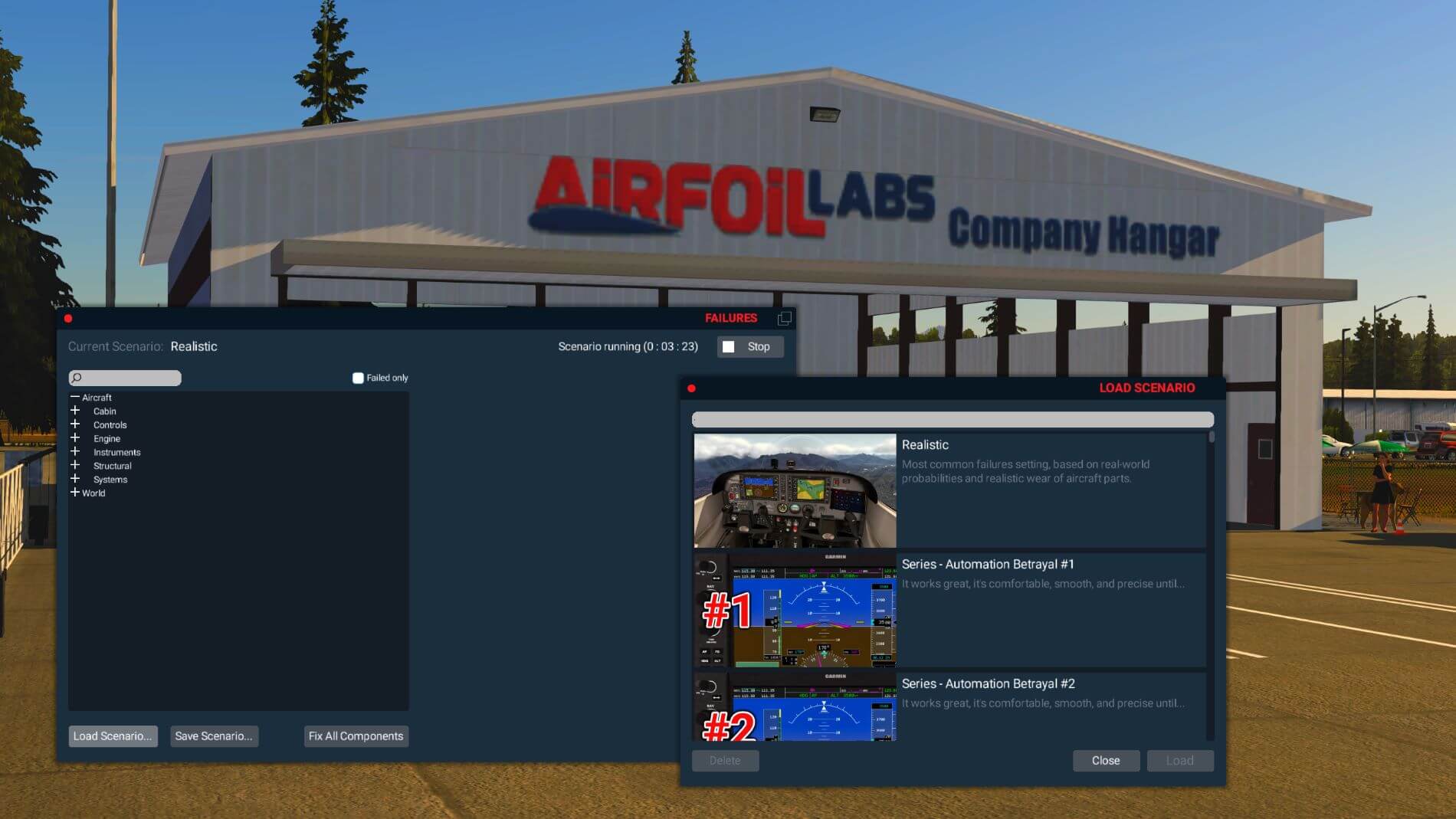
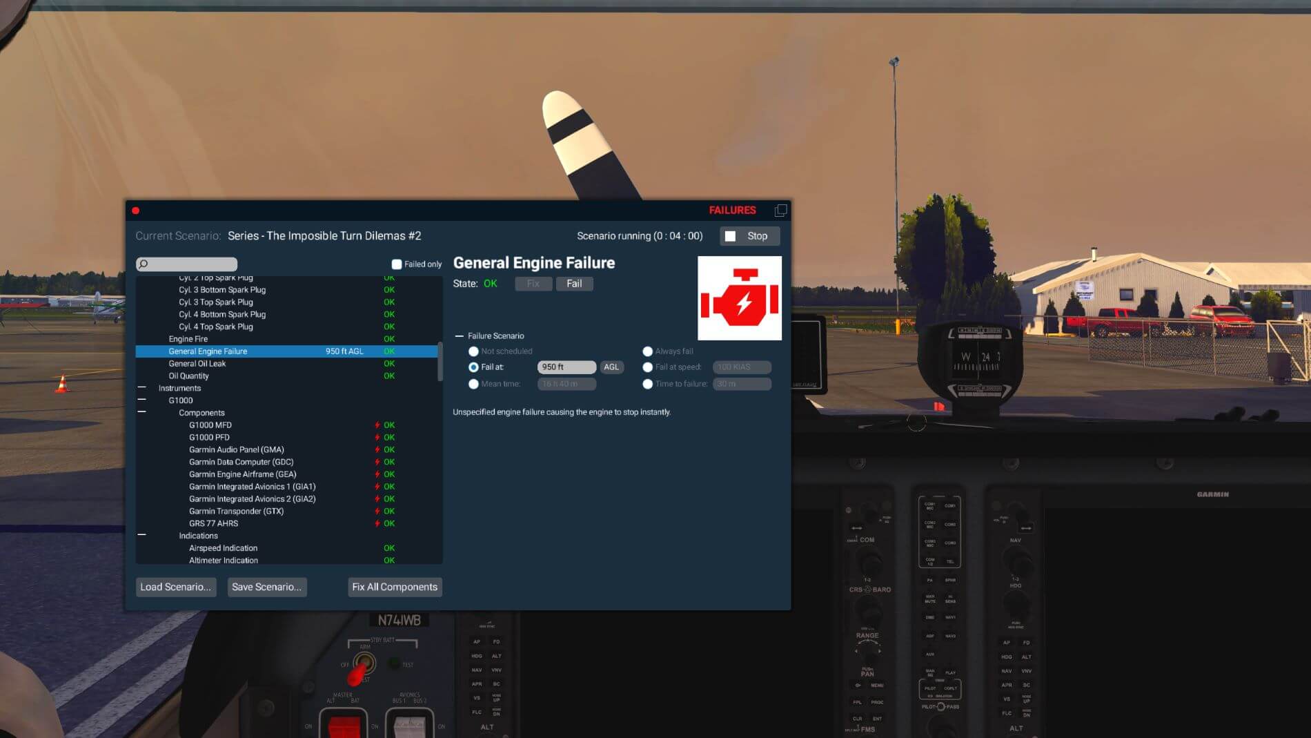
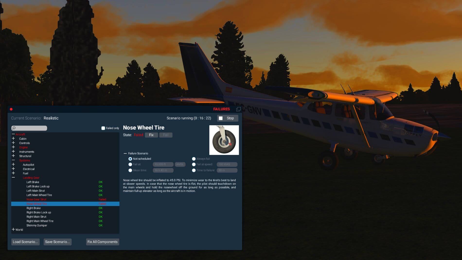
The first column is what will tell you what is going to happen with a specific scenario once you have selected it. The last option in this window is the “save scenario” button that allows you to preserve any customized scenario you have created. Once saved, you will find it at the bottom of the list in the load scenario screen. To close the failure window, you either click on the red dot at the top left or use the failure icon in the pop-up menu that you used to open the window.
Damage Control
Airfoil Labs has you covered when something goes seriously wrong. Not covered in the sense of helping you manage it but in the sense of realistically showing you just what you did to your brand-new airplane. Some of this damage will be the result of flying a scenario and some of it will be the result of flying it in realistic mode and engaging in pilot error or flying the plane in ways it is not suited for. The modelers on the AFL team spared nothing when artfully crafting these things you really hope to not see. Then again, if you’re like me, you’ll take out the plane and abuse it just to see what kind of havoc you can create!
One of the easiest problems for a pilot to create for him or herself is to break the flap actuator. Now you have lost control of the flaps and that can make for a difficult landing especially if the flaps are in one of the down detents, given how this Cessna model likes to float over the airstrip when going any faster than stall speed.
Another break that occurs probably a little too easily is the front wheel strut. I configured the plane with the bush tires and took off from an airstrip on a sandy beach. Just as I achieved roll up speed, the front strut collapsed, and X-Plane told me I blew a tire. On the apron and on the runway, I put the plane through much greater abuse than that before the front strut collapsed. Perhaps tuning is a little too sensitive for off airport operations. Also, you will always have a propellor strike when you break the strut.
Flying over recommended aircraft speeds or making extreme and rapid pitch changes will get you bent or broken wings. The wings have two positions they will bend to without breaking off. Getting that first bend requires little abuse while getting the second bent angle is more difficult since the wing will often break off before it stops at the second angle. The best way to attempt to see the second break angle is to engage in a high-speed dive and attempt to roll out of it. Serious strain on the aircraft results in lost elevators and lost rudders. You know the ground is your next stop when you’ve accomplished this feat. New flight, anyone?


Bending the left and right main gear struts takes a practiced and precise trash landing with all the weight of the aircraft coming down on one side. If you’re really good, you’ll see the sparks flying from that wing that just scraped the ground while you were working so hard to break your landing gear. If you possess an advanced skill in plane wrecking, you’ll have accomplished a nice spark generating tail strike just before you slam down on the side you have chosen to destroy.
If you have accomplished the above, you have most likely found your plane up on its nose, resting on one side propped up on a wing, having a rest on crumpled landing gear, and best of all, for those of us entertained by the wanton destruction of a fine aircraft, one of the best pyrotechnic shows I’ve seen in the X-Plane world. The flames look real enough, and I can almost smell the oil while watching that thick, black, smoke billowing into the air as a result of my handiwork. You can also see that smoke fill your cockpit if you manage to set your engine on fire.
Putting the humor aside now that I’ve finished trying to see what things look like when they break, I have to say that I’m impressed by the detail included in the model. They have taken the time to model the interior structure of the wing that becomes visible when the ends break off. The same is true for the tail section when the rudder fails, or the elevators detach. The missing elevators also reveal the work utilized to create the spars that now protrude into the air. In a tip of the hat to whimsy, engaging in a rapid dive will sent various objects flying into the air around your head.
The bent and detaching pieces, sparks, smoke, and flames, lend heartily to creating a reality no pilot ever wants to see. This is modeling detail that pairs with the attentiveness paid to the engine that we looked at previously. What detracts from the reality is the ability to bend the propellor, restart the engine, take off, and fly like the damage never occurred. One other detraction is the imaginative, well done, sparks do not know how to stop when the metal parts of the airplane are dragging on grass.


Repairing the damage is easy enough and, fortunately, has no expense. You can repair everything in one click by clicking on the repair icon that pops up when you move your cursor over the failure icon in the pop-up menu. You can also go into the parts list of the failure window and repair items individually while reading about the function of the part and what happens if it fails.
Sounds
Now that we have looked at so many of the visuals, we turn to consider the “more than 320” FMOD sounds provided with the Cessna 172 NG.
As I have gone through the evaluation of this aircraft, I have certainly heard many different sounds. The ones I have heard, to my ear anyway, sound realistic enough. Reflective of the quality of work, the sounds never dominate a moment. Rather they remain unobtrusively in the background, except for the G1000 warning chime. It does not take long for that chime to become very annoying, which, I suppose, is the purpose of such a chime just like the seat belt warning in a car. Unlike the seat belt warning, you can turn off the G1000 warning if you choose to. All the other sounds maintain their unassuming role of filling out the immersion experience.
I have lost track of how many sounds I have heard but there are a few that you hear a lot that I will take a moment here to comment on, starting with inside the cockpit. Doors, door latches, window latches, and the grating sound of the window sliding open are all clear, precise, and end the moment the action ends. No early starts or late stops. Switch clicks vary according to the type and size of the switch. Slider sounds are distinct. The start up sequence from priming to the engine catching sound realistic. Plug in the headset and all the cockpit sounds are suitably muted.
While you are walking around the plane, you will hear the engine sound volume increase and decrease as well as change direction. The volume is decreases when standing in front of the plane since the rotating propeller is moving the sound away from you. Standing behind the plane provides you with the sound of air rushing over the airfoils. Ambient sounds in flight do not change externally, but they do change accordingly within the cockpit.
If there is one drawback to the AFL sounds, it is that they do not seem loud enough to balance with the native sounds of XP. In order to appreciate the sounds, I found I had to use my headphones and increase my system volume then decrease the radio volume in XP or turn off AI aircraft so I could still hear the ATIS broadcasts and ATC instructions directed to me. The one sound that seems to be missing is that of the rain hitting the windscreen. With all the effort put into creating those amazing rain effects, it would be quite nice to be able to hear it as well.
Lighting
We finally arrive at the last point of inspection on this very complex and well-crafted aircraft and that is the lighting. I am happy to say that it maintains the excellent level of work seen throughout the model and ranks among the best aircraft lighting I have seen. One feature that applies to all external lights that impressed me is the lack of lighting showing through solid structures such as wing tips.
There are four rheostats on the main panel directly beneath the battery switch that control the avionics, back up gauge, switches, and pedestal lights. These quite satisfactorily take the lighting from entirely off to daytime visible bright. The lit areas do not lose any sharpness or clarity and the G1000 becomes easier to see at night when slightly dimming the light.
Two cabin lights overhead are on at their brightest setting by default. You control these lights by rotating the respective switch to turn them off. They fully illuminate the cabin as soon as the battery switch is in the on position so no more fumbling in the dark to find the switch to turn them on. At the rear of the cabin is a similar light for passengers. This one is a simple on-off switch. This switch also controls the exterior lights that illuminate the under-wing area in the vicinity of the doors. The source of that lighting is not visible.


Beautiful lighting on the interior is not much good if the plane is not useable in the dark. The Cessna is type certified for IFR and night flying and the exterior lights are very functional and support that certification. As previously noted, the physical modeling of the light fixtures is remarkable for its detail. Those physical lights project very lifelike taxiing and landing beams as well as clear and realistic nav, strobe, and beacon lights.
The taxi lights realistically illuminate the area immediately in front of the aircraft and reach taxiway signage with enough time for the pilot to be able to react accordingly. The landing lights turn a dark runway into a very visible touchdown location. All the other external lighting projects into the dark and along ground surfaces as you would expect from each type and color of fixture.
Summary
We have finally arrived at the end of our tour of the Airfoil Labs Cessna 172 NG. The incredible amount of work that went into developing this aircraft is very much on display. With such in depth work covering such a vast scope, I think it is reasonable to expect some areas to be more thorough, accurate, and detailed than others. Airfoil Labs has stated a firm commitment to ensure that this aircraft will continue its life beyond XP 11 and into XP 12. I would think that, given how long AFL intends this aircraft to be viable, there will be future upgrades that will address some of the less strong areas of this model.
That said, the areas that appear to not need much attention include the physical modeling, lighting, damage and crash details, and particle effects. The database of information available for explaining the many parts of a 172 is thorough and useful. A small amount of work here to correct the few formatting flaws should pretty much complete this area. Other than that, I found everything here very well done.
The menu interface is intuitive, easily navigated, and very functional. It provides access to every feature of the aircraft. The inclusion of multiple levels of startup is a very useful and well thought out implementation that allows a person new to the aircraft the chance to work down from seeing what everything looks like right before takeoff down to cold and dark. A quick study allows for observing the changes made at each step so that, once a person learns how to make those changes, they have a good idea of what changes made at what step in the startup process. The exhaustive checklist is a very good aid to that process.
The aircraft handling compares well to another advanced modelling of the C172. This one seems to float a bit more easily but, unfortunately, I am not able to determine which is more accurate. The options available do affect handling as we saw when noticing the speed changes caused by each one. Changes in ground handling occurred when changing tires. The aircraft both responded differently and sounded differently when operating on off pavement surfaces.
The aircraft matched up well to published speeds except for the cruising speed. To be fair, I was unable to achieve that speed with the comparison model I used. Perhaps Cessna is exaggerating their specs a wee bit. Demonstrating a step in their commitment to the model, Airfoil Labs released an update to the aircraft while I was writing this review and changes I experienced are noted within. The largest single difference was reigning in the pitch instability which, apparently, was a result of problems with the elevator performance programming.
The failure and scenario features work very well together and are very specific. There are enough parts for the pilot to fail individually or together to create as complex a flight situation as possible. I found the predefined scenarios interesting in that I had no idea what as going to happen or when it would happen. Some things occurred that did not affect my flight and I would have never known they happened until I checked the failure list to find the failed item. These items tended to be the type that would demonstrate a problem over time if the pilot did not get it repaired. Other failures necessitated an immediate landing, and some resulted in discovering just how well modeled the damage effects are.
All the above comes together to make this an exceptional airplane and unique enough to make a significant difference from the default C172. While there may be some technical aspects that make a difference to the most detailed and knowledgeable C172 real life pilot, I do not see anything related to the physical and performance model of this aircraft that does not make it worth the purchase price for someone interested in the more in-depth workings of this Cessna along with the wealth of information compiled for the informational database.
Unfortunately, the model does suffer from one big problem: a total lack of documentation.
As of this writing, Airfoil Labs stated that the documentation would be a series of video tutorials published to YouTube. Currently, those videos total four and not one of them covers starting the aircraft from cold and dark or where to find the checklist. I must consider this a serious oversight on the part of the developers. A welcome video screen is an unnecessary stumbling block since I have never seen this done before and the click point on the “Take Control” banner did not immediately appear obvious. Once having cleared that, and figuring out how to disable it, I found myself sitting in a cockpit with no indication of where to go from there.
It was only by pure accident that I found the airplane manual in the door pocket and happened to notice that it also contained the process for starting the Cessna. A few trips out to the support forum showed me that I am not alone in feeling a bit aggravated by this. More than one person did not realize the checklist was in the manual thinking it was only a two-page document illustrating the dimensions of the plane.
This is not my first X-Plane aircraft and I have started all – many more complex – from a cold and dark state. I learned how to start a Cessna 172 by using a detailed add on to the default 172 that would brook no error. These were all learned by reading the documentation that comes with the model. With that experience I approached the AFL model as I had learned on the above-mentioned model. The startup used by the AFL model is just different enough that I was unable to start it. It took more time than it should have to figure out what was different and how to work with it given that this aircraft is, at least in part, directed to the new student pilot.
My final critique about the documentation is I personally do not think video tutorials should be the sole implemented teaching mechanism. It is difficult to operate the aircraft in X-Plane while running a video at the same time. Many people learn best by doing and accomplish that by following instructions step-by-step. In the absence of an instructor standing in the room providing those steps, printed documentation is essential. Some things need to be explained more in depth than what a simple checklist can provide.
The lack of documentation is what motivated me to make this review quite a bit longer than it would otherwise have been. It is my hope that, as well as looking at the quality of the model and evaluating it from an add on to X-Plane perspective, this review can serve as a getting started manual for pilots new to X-Plane and new to an aircraft presented as in depth as this one is.
My bottom line for the Airfoil Labs Cessna 172 NG is a very strong thumbs-up. I have enjoyed immensely the immersion and interactivity this aircraft provides. Walking around, removing tie downs and covers, checking fuel and oil, and climbing on the wings to fill the tanks with fuel is the closest I have felt to performing an actual pre-flight inspection and preparation. I have been very satisfied with the learning experience provided by the informational dialogues, and I have been pushed to research some things further.
Thanks to the G1000 implementation of leaning, I now know exactly what that is, why to bother with it, and how to do it. I have learned more about the aerodynamic forces on airframes and flight surfaces than I knew before and that is only going to help me fly my other models with a greater sense of doing it right. Regardless of the debate, for me, this aircraft is, indeed, “study level”. Well done Airfoil Labs. Please remedy the documentation this model so richly deserves.
Until next time, cheers and blue skies, Captain.
More information can be found at the dedicated Aerosoft store page, at the X-Plane.Org store and of course, additional information can be found at the Airfoillabs website.
Feel free to contact me if you’ve got additional questions related to this impression. You can reach me via email Angelique.van.Campen@gmail.com or to Angelique@X-Plained.com.
With Greetings,
Paul Beckwith
| Add-on: | Payware Airfoillabs C172 Next Generation Skyhawk |
|---|---|
| Publisher | Developer: | Aerosoft / X-Plane.Org | Airfoillabs |
| Description: | Realistic rendition of Cessna C172 Digital |
| Software Source / Size: | Download / Approximately 3,12GB (unzipped) |
| Reviewed by: | Paul Beckwith |
| Published: | January 22nd 2022 |
| Hardware specifications: | - i7-10870H CPU @ 2.20GHz - Nvidia GeForce RTX 3080 Laptop GPU - 16 GB DDR4 3200MHz RAM - CH Products Fighterstick - Dual Saitek Throttle Quadrants - CH Products Pedals |
| Software specifications: | - Windows 11 - X-Plane 11.55 (64 Bit) |
2 Comments
Submit a Comment
You must be logged in to post a comment.
I liked the sparks and the fires
🙂