Impression | FlyJSim Inertial Navigation System
Meet the Old Fashioned INS
This review is, in one-way or another, a part of my previous FlyJSim Boeing 727 Series review. The simulated INS (Inertial Navigation System) is a perfect companion for the Boeing 727 since, without this piece of hardware, navigation has to be done with the help of VOR (VHF Omnidirectional Range) or NDB (Non-Directional Beacon) stations. In case you’re not really familiar with VOR stations or NDB beacons, see the above Wikipedia links. Of course, many other websites are available that offer you thorough background information about these navigational aids.
Originally, the Boeing 727 didn’t have the Delco Carousel INS, but retrofit packages allowed airliners to install the INS. Later 727 aircraft were even equipped with FMS (Flight Management System).
By the way, Delco Carousel was a popular INS-based navigation automation system for aircraft developed by Delco Electronics. Before the advent of sophisticated flight management systems, the Carousel system allowed pilots to automate navigation of an aircraft along a series of waypoints that they entered via a control console in the cockpit. The Carousel used an INS as its position reference for navigation. Many aircraft were equipped with dual or triple Carousels for redundancy. The Delco Carousel derives its name from the fact that the inertial reference platform is in constant rotation as a technique to reduce drift and increase accuracy.
The idea of this review is to highlight the X-Plane developed CIVA INS and how to implement the INS in the FlyJSim 727. Also, you can use this CIVA INS in combination with other “old-fashioned” XP aircraft. Actually, the provided INS is no more then a plug in that needs to be installed in the aircraft plug in folder. But first, let me give you some background information about the operation and functionality of the CIVA INS.
Some Basics
Basic Construction
Consider an accelerometer as an instrument that measures acceleration along a single axis.
Integrate the output once, and you have velocity. Integrate again, and you have position, or rather, change of position along the accelerometer’s axis. If you know the direction of travel, you can deduce current position.
Inertial Navigation is simply a form of dead reckoning. You need to know the starting point.
An Inertial Navigation device/system can’t find its initial position on the earth (it can find latitude, with difficulty, but not longitude).
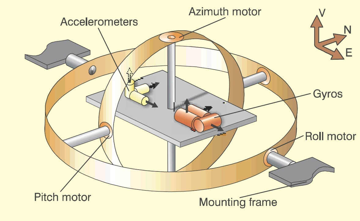
Take three accelerometers, with their sensing axes orthogonal. Arrange them so that their axes are aligned north south, east west, and vertical. To maintain this orientation when the vehicle maneuvers, the accelerometers are suspended in a set of three gimbals that are gyrostabilized to maintain the direction. Later, we’ll be describing strap down arrangements, but it always seems easier to explain the principles by starting with the gimbal model.
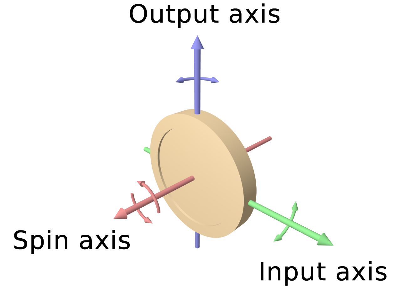
The gyros, similarly, are single axis devices of a type known as integrating gyros.
That is, they give an output proportional to the angle through which they have been rotated about their input axis. The gyros are used as the sensing elements in null seeking servos, with the output of each gyro connected to a servomotor driving the appropriate gimbals, thus keeping the gimbal in a constant orientation in inertial space.
Integrating gyros also have what is called a `torquer’, which is a means of processing the input axis at a rate proportional to input current.
This forms a convenient means of canceling out any drift errors in the gyro. The gimbals, as shown in the figure, (well, they may be there, but they’re not identified) have a bearing at each end. Each has a motor, built around one of the bearings, and at the other end a synchro.
No matter how the aircraft maneuvers, the innermost gimbal maintains its orientation in inertial space. The synchro on the innermost gimbal thus measures azimuth (or heading), the synchro on the middle gimbal measures pitch and the outer gimbal measures roll.
The innermost gimbal can be thought of as a stable platform on which are mounted the gyros and accelerometers although, in practice, it looks like anything but a platform, being a miracle of mechanical packaging.
The whole arrangement is generally called a gimballed platform. You’ll find on your left an example of an Inertial Measuring Unit (IMU), which houses not only the gyros, motors and gimbals, but also the accelerometers.
Simplified operation
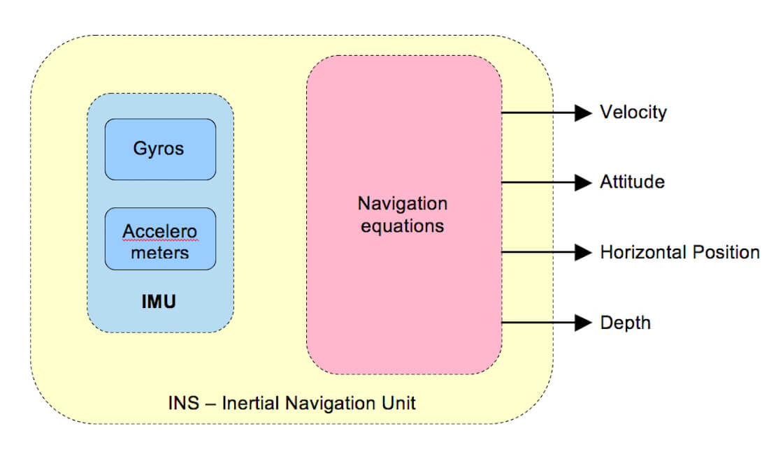
As I said before, the IMU is an electro-mechanical device consisting of accelerometers and gyroscopes. The accelerometers are mounted on a gimballed platform in a way that the axis of the devices sensitive to acceleration were mutually perpendicular.
At the beginning of the flight, an IMU is aligned, although some say incorrectly that the INS is aligned. Just so you understand, INS is a system, with all of the components together like the IMU(s), Mode Selector Panel(s), CDUs (Control Display Unit) etc. The pilots provide the CDU with the current position of the aircraft. The system stores this information and also aligns the gimballed platform to a set attitude with reference to the Earth.
The gyroscopes were set up to measure the rotational displacement and velocity of the aircraft about the longitudinal, vertical and lateral axis of the aircraft.
Basically, what happens is that the gyroscope signals are used to mechanically rotate the gimballed platform in a direction opposite to the aircraft.
This maintains the accelerometers in the same attitude, relative to the Earth, that they were established in during the alignment process. Thus, if one accelerometer was aligned East-West and one North-South, this alignment would be maintained no matter the attitude of the aircraft.
The accelerometers would generate signals proportional to the accelerations in the E-W and N-S directions. This acceleration data can be directly integrated once to get velocities in the E-W and N-S directions and integrated once more to get displacements or navigation data in the E-W and N-S directions.
Good, I hope you’re still with me?
Parts of the above are derived from the Aalborg University, department of Electronic Systems, AeroStudents.Com. But there’s so much more on the Internet.
Lets move on to the XP10 installation and documentation.
Installation and Documentation
General
The X-Plane developed CIVA INS can be found at the dedicated X-Plane.Org web page.
According to X-Plane.Org, The original CIVA INS could be found on the Boeing 707, 727, some 737-100s and -200s, the DC-10, L-1011 Tristar and on the early 747-100, -200 and -300 variants. This simulated CIVA INS unit has primarily been developed to be used with the 727 series of FlyJSim however, it can be installed with any other aircraft.
The CIVA INS package comes with the following features:
– Fully compatible with the 727 Series by FlyJSim
– Realistic warm-up, initialization and alignment procedures
– Optional Quick-Align to get you flying instantly
– All display modes modeled, including HOLD modes
– Automatic navigation of up to 9 waypoints
– XP flight plans can be loaded instead of manual WP entry
– Single-DME updating incorporating DME elevation
– Realistic position drift and smooth updating
– Built-in 30-minute backup battery in case of emergency
The CIVA INS manual can be download before buying the product, by using this link. It gives you, in advance, an idea of what to expect if you decide to buy this add-on package. Since you can use it with other old-fashioned XP aircraft, it’s a multi functional plugin and therefore $10.00 US or approximately 8,25 Euros (mid May 2013) isn’t much money.
User Guide
OK, once you’ve bought the package, downloaded (xciva.zip | 3.9MB) and unzipped it, you end up with a folder “xciva”. It contains:
– the actual plug in xciva (32/64 bit XP)
– CIVA-User-Guide.pfd
Let’s start with the user guide. The User Guide comes with the following chapters:
– Inertial Navigation – An Introduction
– Installation
– The CIVA Pop up window (via XP menu)
– Keyboard entry, basic modes and navigating
– The Hard mode (Cold & Dark situation)
– Display modes
– Leg change and DME updating
Although the manual seems to offer all the information that’s needed to understand CIVA INS, it’s not written in a user friendly way, in my opinion. For example, chapter 8 has far too much text and hardly any pictures to highlight certain process changes or visualize the steps to be taken. It looks like a tutorial, but for sure it’s not my favorite layout. At least, a dedicated tutorial for a complete flight is needed. If you’ve never worked with the CIVA INS, then you’ll have a hard time due to the absence of a tutorial.
Perhaps, and I say perhaps, if time permits, I’ll try to write a CIVA INS tutorial for use with the FlyJSim 727.
INS Videos
Searching YouTube for the CIVA INS operation, I found four movies that could be of interest. These videos show you a different INS CDU, not the one developed for X-Plane, but it should give you a better understanding how to handle this INS CDU and the Mode Selector Unit.
– CIVA INS tutorial I
– CIVA INS tutorial II
– CIVA INS tutorial III
– CIVA INS tutorial IV
FlyJSim 727 Installation
Next step – where to install it?
If you use the CIVA INS in combination with the FlyJSim 727, then it’s quite simple. Install the “xciva” folder in the “Aircraft/727-200Adv/plugins”, “Aircraft/727-100/plugins” or “Aircraft/727-200F/plugins”.
But as we said before, any other old-fashioned aircraft could use CIVA INS too. In that case, if that specific aircraft doesn’t have a subfolder called plug ins, you must create one. When you’ve loaded the FlyJSim 727, on the left hand side of the screen you’ll see some icons. One is named INS. When you click on it, the INS icon gives you the CIVA INS CDU. That’s provided you’ve installed it in the 727 plugins folder, as explained in the manual and previous paragraph.
Any other aircraft?
I didn’t try them all, but I did check it on the default Beechcraft Baron 58. This aircraft doesn’t come with a plug ins folder, so you need to make one. After that, the only thing you need to do is to copy and paste “xciva” in this folder. At XP start-up, select the Baron 58 and by selecting the XP plugins menu you can chose CIVA. And there you are … the CIVA INS!
Testing the CIVA INS
Initial setup with the FlyJSim 727
Although you can decide to go for the easy way, which means that the CIVA INS is already warmed up, initialized and aligned, I prefer to go for the hard way. That means a 727 without engines running, no electrical power connected thus starting from a cold and dark situation.
It’s not a complicated procedure as long as you read item 8 in the user guide carefully and that you power up the 727 as described in the 727 manual. I think one of the hardest things is to get the correct latitude/longitude position. The AirNav website offers much information about your selected airport, but I haven’t seen a list of LAT/LON per gate or parking position and that’s what you want. Or not!
Personally and suggested in the user guide, I would go for the DirectionsMag.Com website. If you go for this, via XP menu, first activate “Data Input & Output – tab Data Set”, item 20 (lat.lon.altitude).
Consequently, on your screen, on the left hand side of the pop up window, you’ll see the lat and lon values and much more information.
Let me give you an example (also see the screen shot on the left). My current review position has a “lat” that equals 47.45 deg and a “lon” of 122.3 deg. With the help of the DirectionsMag website, you’re able to convert them into degrees, minutes and seconds. My 47.45 deg will become N47.27.0 (degrees, minutes, seconds) and 122.3 deg will become W122.18.0 (degrees, minutes, seconds). These last two values – N47.27.0 and W122.18.0 – must be entered in the INS section 8.
Once the alignment process is completed, you can load your FMS flight plan or manually enter all way points. The easiest way is to create a flight plan you have in mind, place it in the XP folder “Output – FMS plans”, but beware of one thing. If you’ve got a bunch of flight plans in this folder and you’re flight plan is, alphabetic order wise, not within the range of the first 9 flight plans, you won’t see it in your INS CDU. This procedure is described in section 7 of the user guide. So, be sure to take care that the FMS plans folder doesn’t have more then 9 flight plans. Yours included.
Here’s another issue to keep in mind. The CIVA INS can only use flight plans with the XP extension “fms”. Like the JARDesign A320neo, this dedicated FMS uses “txt” flight plan extensions. You shouldn’t use this “txt” extension for use with the CIVA INS!
As indicated in the user guide, during your flight, you can now use the INS CDU by placing the AP NAV SELECTOR to AUX NAV.
A typical INS flight impression with the FlyJSim 727
Once I completed all my FlyJSim 727 preparations, CIVA INS warmed-up, initialized and aligned, I loaded my EBBRLFBO.fms flight plan (a typical flight plan from Brussels, Belgium (EBBR) to Blagnac Toulouse, France (LFBO), I’m ready to go.
I’ve decided to takeoff from runway 7L, but you could also take 25R. Being airborne, I first select the AP servo lever for maintaining a certain Vertical Speed, followed by placing the right hand selector on the AP panel to AUX NAV. This connects the CIVA INS to the aircraft Auto Pilot. Depending on the data selector knob, by doing this, the INS CDU shows you the actual latitude/longitude position (POS position).
The following screen shots, with descriptions, show you what you see when flying from way point 1 to 2, where way point 1, the first way point after takeoff is located. Then after a while, the CDU FROM-TO indicator shows “2 3”. This means you’re now flying from way point 2 to way point 3 etc.
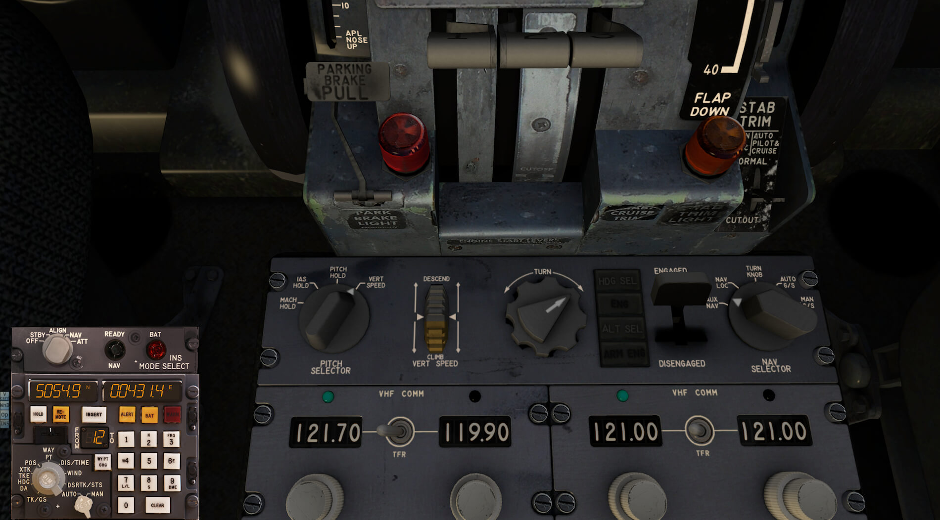


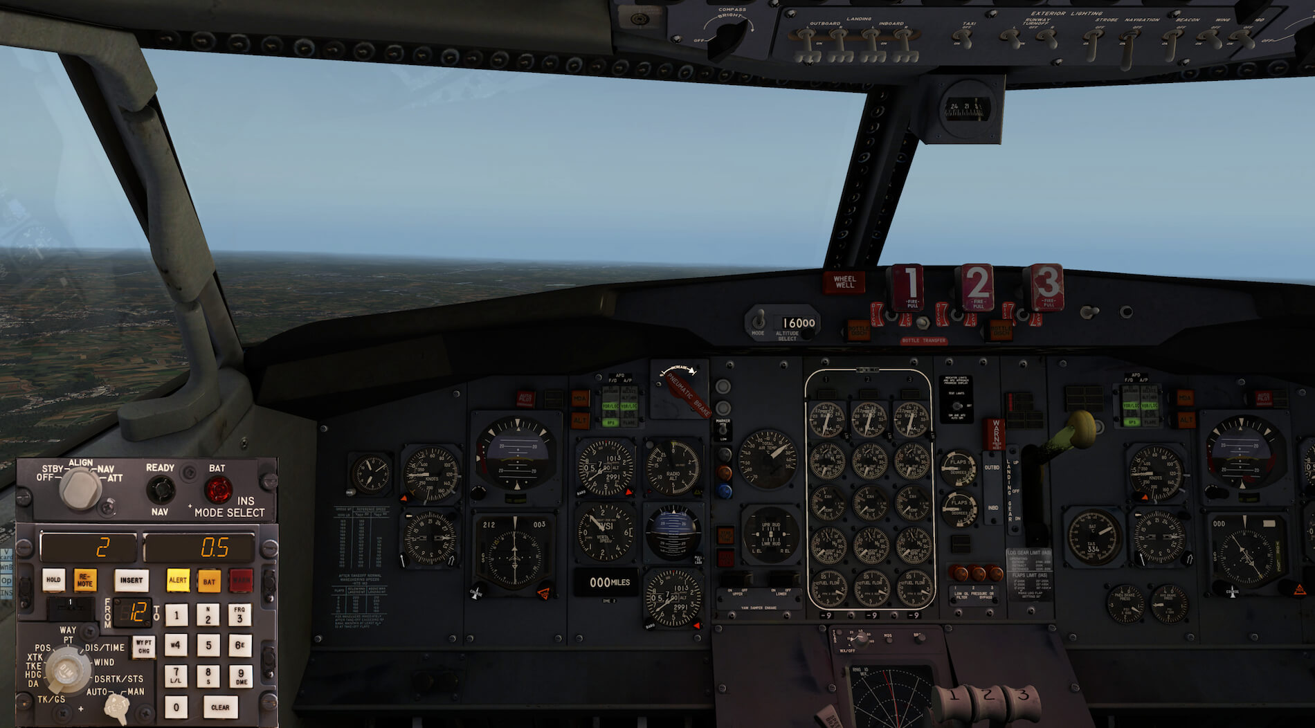
Screen shot 1 shows the FlyJSim 727 AP panel with the servo lever engaged, NAV SELECTOR switch in AUX NAV and the PITCH SELECTOR in the VERT SPEED mode. Screen shot 2 shows the data selector switch in POS. The actual aircraft latitude/longitude positions are shown on the CDU display. On screen shots 3, 4 and 5, the data selector is moved to the DIS/TIME position. Consequently, the left hand display shows the distance in NM (Nautical Miles) to way point 2 while the right hand display show the time to reach way point 2.
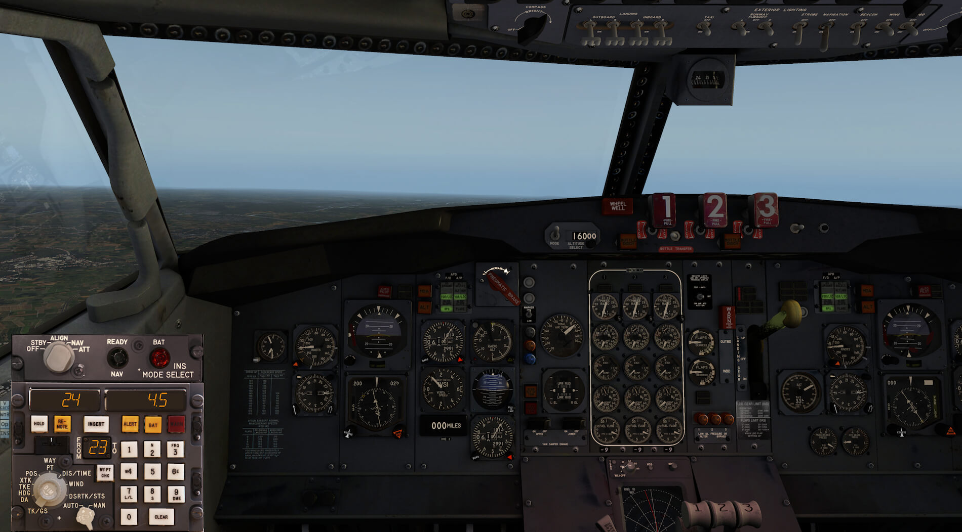
We’ve just passed way point 2 and therefore screen shot 6 shows you that we’re now flying from way point 2 to 3. With the data selector still in the DIS/TIME position, the displays show that way point 3 is 24NM away and with the current speed it will take 4.5 minutes to get there.
It’s not my intention to write down what every “data selector” position represents, since all of this is described in section 9 of the user guide.
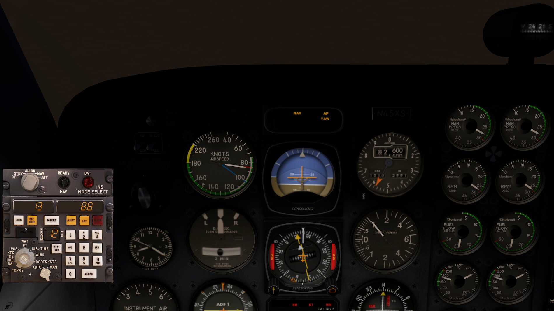
Flight testing on the default Baron 58
A quick test taught me that using the CIVA INS in combination with the default Baron 58 is quite difficult although effective. To get the CIVA INS connected, take care that the HSI selector is in the GPS position and, on the AP panel, that you select NAV. Once you’ve done that, the INS will guide the Baron 58 according to the loaded flight plan.


Anything forgotten?
Perhaps I have!
You never know if I’ve forgotten something, but I think I’ve tested and seen it with my own eyes. The CIVA INS is working great with the FlyJSim 727 and, importantly, it adds another old-fashioned device to the FlyJSim 727. These two add-on products work perfectly together. The only suggestion I could think of is that perhaps Jack from FlyJSim, could make a dummy Mode Selector Panel on the overhead panel and a CDU on the forward side of the pedestal. Made in such a way that if you click on either panel, the combined CUD/Mode Selector Panel pops up. I’m aware that doesn’t bring any additional functionality, but it makes the 727 complete.
Summary
This software package is still one of my favorite add-ons. It doesn’t mean I don’t like Boeing or Airbus Auto Flight systems with FMS, but this goes back to the basics of navigation. In combination with the FlyJSim 727, it adds something to this extraordinary aircraft. Flying the FlyJSim 727 from VOR or NDB station to the next station, means a lot of work. Adding the CIVA INS to this aircraft relieves you of a lot of the navigational work and provides you with lots of fun.
The installation in the FlyJSim 727 is simple and with the FlyJSim INS icon on the left hand screen, the call-up of the INS CDU is even simpler. As we mentioned earlier, the user guide offers all the information that’s needed, however, the way it’s presented is not always simple. For those who are new to the CIVA INS CDU, this user guide isn’t really very helpful. Although I found some YouTube videos, a written tutorial would be welcome.
And, as I wrote somewhere in this review …. perhaps and I say perhaps, if time permits, I’ll rewrite one of my Commercial Level Simulations DC-10/747 Classic CIVA INS manuals for use with the FlyJSim 727.
Finally, according to what’s on the X-pPlane.Org website, this CIVA INS plug in can be used in combination with any other aircraft. That part I haven’t really tested, since the CIVA INS is basically developed for use with the FlyJSim 727 and that was my goal.
More information about the CIVA INS package can be found at X-Plane.Org. As of this writing, the CIVA INS cost you $ 10.00 US or approximately 8,25 Euro’s (mid May 2013)
Feel free to contact me if you’ve got additional questions related to this impression. You can reach me via email Angelique.van.Campen@gmail.com.
With Greetings,
Angelique van Campen
| Add-on: | Payware CIVA xINS Inertial Navigation System |
|---|---|
| Publisher | Developer: | X-Plane.Org | Philipp Münzel |
| Description: | Realistic rendition of the CIVA INS |
| Software Source / Size: | Download / Approximately 9MB (unzipped) |
| Reviewed by: | Angelique van Campen |
| Published: | May 23rd 2013 |
| Hardware specifications: | - iMac 27″ 3.5Ghz Late 2013 - Intel i7 3.5Ghz / 3.9Ghz during Boost Mode - NVIDIA GeForce GTX 780M 4096 MB - 32 GB 1600 MHz DDR3 - 1 internal 1TB SSD (El Capitan 10.11.4) - 3 external 1TB SSDs - Saitek Pro Flight System |
| Software specifications: | - El Capitan (10.11.4) | Yosemite (10.10.5) | Mavericks (10.9.5) - Windows 10 Professional - X-Plane 10.45c | X-Plane 10.45m |
0 Comments