Meet FlyJSim’s Boeing 727 Professional v3
Introduction
Again, a long review although I did expect it. It turned out that this FlyJSim 727 Professional v3 review has become a bit longer and because of that, I’ve decided to add a Table of Contents, so here we go.

Table of Contents
Introduction
Relive the Glory days of the 70s
Installation and Documentation
– How to Install?
– Documentation
– Liveries
First Things First
– Screen Icons
Walk-Around Inspection
The Cockpit
First Flight Impression
Second Flight Impression (Using VOR / VORTAC)
Third Flight Impression (Using FMS)
– Introduction
– Flight plan Creation
– My KDAB to KEYW Flight
Surprise … Meet the Old Fashioned CIVA INS
– The INS
– Basic Construction
– Simplified Operation
– The xCIVA INS Add-On
– Package and User Guide
– Installation
– INS Videos
– Using xCIVA INS
Fourth Flight Impression (Using xCIVA INS)
– Preparations
– The Flight
Anything Forgotten?
Summary
Introduction
Let’s go back to the good old days, back to the famous tri-jet known as the Boeing 727 Series or was the 727 known as “Whisperjet”, “3-holer”, “Tri-jet”, “Trisaurus”, “Triple Chrome-plated Stovepipe”, “Jurassic Jet” and finally also known as “Ear Blaster”. I would say, the more nick names it has, the more we can say that it was a successful aircraft and it was!
Many manufactures tried to copy this like Tupolev with their Tu154 Series, the British Aircraft Corporation Bac One-Eleven, the Hawker Siddeley HS 121 Trident, the Dassault Falcon 900 or 7X, although the Dassault Falcon aircraft was more a business jet and not to forget the Lockheed L-1011 TriStar, but again, this is a much bigger aircraft so not really listed in the medium sized 727.
Long story short; the 727 was a great success and believe it or not, they are still flying around, mostly as freighters.
For some, the 727 was and still is a nightmare. For others, it’s the ultimate tri-jet. Whatever it was, in those days, it was a special aircraft …. Meet the Boeing 727 Series.
I never worked as ground engineer on this aircraft, but I must say that it is indeed a beautiful model. Beautiful or not, it’s more important to find out if this FlyJSim 727 is the ultimate trijet aircraft, in particular for those who prefer to fly the old-fashioned way, either with the help of VOR/VORTAC beacons or with the default Laminar Research FMS MCDU or the xCIVA INS add-on.
Relive the glory days of the 70s
It’s always interesting to have some knowledge about a famous aircraft like the Boeing 727 Series. The best way to find out more is to visit the one and only source …. the Boeing Commercial Airplanes dedicated historical 727 website.
The versatility and reliability of the Boeing 727 — the first trijet introduced into commercial service — made it the best-selling airliner in the world during the first 30 years of jet transport service. The jet age essentially began in 1952 with the introduction of the British-designed de Havilland Comet. Several jetliners, including the Boeing 707, were developed before the 727, but none came close to its sales record.
Production of the 727 extended from the early 1960s to August 1984, which is a remarkable length of time, considering the original market forecast was for 250 airplanes. As it turned out, 1,831 were delivered. Twenty years later, when the last 727 was delivered, this versatile fleet was carrying 13 million passengers each month. As of January 2001, nearly 1,300 of the reliable aircraft were still in service.


Introduced into service in February 1964, the 727 trijet became an immediate hit with flight crews and passengers alike. With a fuselage width the same as the 707 (and the later 737 and 757), it provided jet luxury on shorter routes. With sophisticated, triple-slotted trailing edge flaps and new leading-edge slats, the 727 had unprecedented low-speed landing and takeoff performance for a commercial jet and could be accommodated by smaller airports than the 707 required.
The 727, like all Boeing jetliners, was continually modified to fit the changing market.
It began with the -100 series, of which 407 were sold. This was followed by the -100C convertible, that featured a main-deck side cargo door, allowing it to carry either cargo pallets or passengers, or a combination of both on the main deck. Boeing built 164 of these.
The 727-200, introduced in December 1967, had increased gross weight and a 20 foot longer fuselage that could accommodate as many as 189 passengers in an all-tourist configuration. In all its variations, 1,245 of the -200s were sold.
The last version, the 727-200F, had a 58,000-pound, 11-pallet cargo capability. Fifteen of these were sold to Federal Express.
On December 5, 1977, the worldwide 727 fleet carried its one billionth (1,000,000,000) passenger. That was a mark never attained before by a commercial aircraft. Today, the number has reached well over 4 billion.
One hundred and one customers purchased new 727s from Boeing, although dozens more have placed this airplane type into service as “second tier” operators. More than 300 727s built as passenger airplanes have been converted to freighters, a process that continues today.
For more information, I encourage you to visit the dedicated Boeing Commercial Airplanes 727 Series web pages. But there’s so much more. For example, here’s a link to YouTube that shows you the Boeing 727 Prototype-“First Flights”-1963/64.
Installation and Documentation
How to Install?
First, you need to unzip the 4 packages including that of the manual. Actually, you need to download the following ZIP files:
– 727_Series_Pro_V3_-100
– 727_Series_Pro_V3_-200Adv
– 727_Series_Pro_V3_-200F
– 727_Series_Pro_V3_Manuals
It doesn’t come with an installer, thus after you’ve unzipped each package, copy and paste these to the Aircraft folder or create your own FJS (or FlyJSim) folder within the Aircraft folder. This means, you will end up with three 727_Series_Pro_V3 packages.
Each model comes with a couple of liveries and those added and uploaded by painters, could follow a specific naming convention although it’s not really needed:
– 721 (for the 727-100 Series)
– 722A (for the 727-200Advanced)
– 722F (for the 727 Freighter)
A couple of words about v2 and v3 liveries; can you use the v2 liveries for the v3 package? I decided to contact Jack from FlyJSim to help me out with this. According to Jack “Version 2 liveries can be used, but we don’t prefer users do that. They are only 2K, and are not updated with all the necessary art assets that give you that full version 3 experience. We will have adding all approved v3 liveries in a list on our website for users to find easily.”
For the activation of each individual FJS 727 aircraft you need a serial number which is, in case you’re lost, for every model the same. For the easiest and fastest way to update the 727 models “SkunkCraftsUpdater.1.xx” is used. I tested it myself and must say … very easy. More information about how to use the SkunkCraftsUpdater can be found in the FJS 727 Series Manual page 11.
Documentation
The FJS package comes with in total 4 Acrobat manuals:
– 1. FJS 727 Series Manual (37 pages)
– 2. FJS 727 Series Procedures (61 pages)
– 3. FJS 727 Series Manoeuvres (35 pages)
– 4. FJS 727 Series Systems (74 pages)
OK, let me first start with the 727 Systems manual. Although a manual is just a manual, knowing the in-depth system programming of FlyJSim aircraft, I urge you to read this system description manual and not just to skip it or “I know it all”. The manual is very nice, full with useful information and worth to print it or when you want to save the world, you read it on a tablet or smart phone.
The 727 Series manual deals with all kind of chapters that range from the installation procedure (it seems to me that the installation procedures only shows screenshots/description for Microsoft Windows), the configuration, the FJS options and the menu. This also includes the activation or registration of the aircraft.
The 727 Procedures and Manoeuvres manuals offer you different procedures and preliminary cockpit preparations. This section can’t be seen a tutorial although it offers all the steps to go thru the simulated aircraft systems. But the other procedure section like “before-start” is a good guideline how to handle the engine systems.
The manoeuvres manual offers all sequentially to follow flight phase and where to think about. Theoretically, these two manuals combined could be seen as a tutorial flight. Since I know the FlyJSim 732 too, I had hoped that a tutorial would have been added to this aircraft since the FlyJSim isn’t easy to use and that’s because many systems are simulated thus “as real as it gets”.
Liveries
Not normally a section I spend too much time with, but this time I do. I have mentioned already after consulting Jack from FlyJSim that the old version 2.0 liveries can be used for this v3 package, but Jack strongly suggested to create new up-to-date liveries that support all the X-Plane 11 features as well as created using the 4K format. That said, the amount of stock liveries included with the three different 727 Professional v3 models are a bit limited in my humble opinion. On the other hand, many painters have already created awesome liveries – as per August 21st 2018 – like for example X-Plane.Org users Atarium, MauB, ArticPilot, Lava.K9, Msp753nwa, KJO and fscabral. Want to see more? Then it’s also worth to check our own download liveries section at X-Plained.Com.
First Things First
Screen Icons
Before I start with my “first flight of the day” inspection, I have the choice, as mentioned before, of the -100, -200 Advanced or -200F. I’m going for the –200F Series. By the way, I know, I mentioned this before, each 727 aircraft has to be activated individually thus activated online the 727-100 won’t automatically activate the -200Advanced and the -200F! Keep this in mind!
Now that I’ve decided to go for the freighter model, I think it’s a good idea to highlight a few small FlyJSim icons on the mid left-hand side of the X-Plane screen. They are identified as “Takeoff/Landing V card”, “Weight & Balance”, “Options”, “Maintenance System” and “Pilot Notes” thus Checklist.

Takeoff/Landing V card offers you the V1, VR and V2 speeds for the takeoff and landing based on the actual A/C parameters. For example, when you change the amount of fuel, the Takeoff speed card is automatically adjusted to the new values and accordingly to the new speeds.
The Weight & Balance popup allows you to add or remove passengers and cargo as well as fuel. Whatever you do, the center of gravity indicator is automatically adjusted accordingly. Very handy and a must for the serious 727 flight simmer.
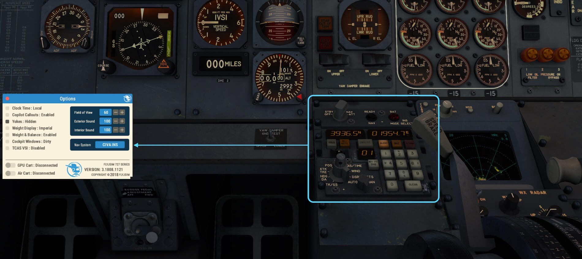
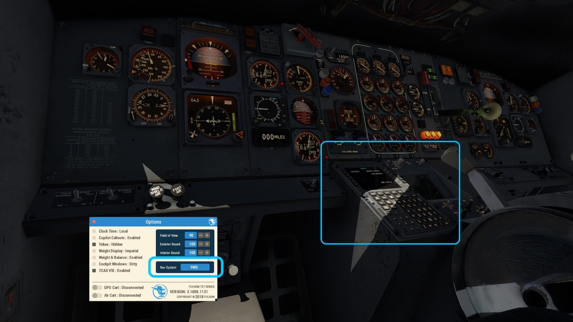
The Options popup allows you to change for example the FOV (Field of View), exterior and internal sound levels, hide the yokes, change the weight from imperial (pounds) to metric (kilograms). With one click you can set the time to Zulu and have the default FMC in 3D view and when you click on it, also in 2D. Of course, it’s up to you, but the default 727 had only an INS CDU and no FMS therefore, when you own the xCIVA INS, it will be also on the Options list. Another nice feature is changing between the old fashioned IVSI (Inertial Vertical Speed Indicator) and the modern digital TCAS VSI.
And last but not least, same as we’ve seen with the 732 v3, connecting/disconnecting a GPU (Ground Power Unit) and an air cart, however, this is pure what you see in the cockpit overhead panel. It won’t simulate a GPU or Air object externally.
The Maintenance System allows you to repair on the fly but as far as I can see, it doesn’t allow you to introduce specific failures. In other words, unless I’m incorrect; you can switch ON or OFF the failure system, but when ON, it randomly introduces failures which is when I’m honest, as real as it gets! The popup is divided into a Status and Reports tab. The Status shows you the actual status of the aircraft systems.
The Pilot Notes or the checklist is what is says, but keep in mind, it isn’t an interactive checklist neither less, it’s handy, and for such a complex old-fashioned air craft worth to use it.

Some words about which navigation equipment you’ll use to fly this FlyJSim 727. You can via the Options menu choose for no aids thus just the ordinary way flying with VOR/VORTAC and/or NDB beacons. Or you go for the xCIVA INS (add-on payware) and finally, you can decide to go for the default Laminar Research FMS MCDU and not, in case you think this is an option too, for the X-FMC.
Regarding the xCIVA INS; CIVA INS or Delco Carousel IV-A Inertial Navigation System Control Display Unit uses the term CIVA as it is just a nickname for the INS CDU. The CIVA can be found on Boeing 707, 727, some 737-100s and -200s, the mighty three-jet DC-10 and L-1011 Tristar, and on the early 747-100, -200 and -300 variants.
Unlike GPS or radio navigation, inertial navigation systems work fully autonomously and don’t require any equipment or installation outside the aircraft itself.
Depending on what’s selected, a designated place at the pedestal is either empty (no navigation equipment used), offers a full functional CIVA INS CDU or a functional FMS MCDU.


Walk-Around Inspection
From a distance, the FlyJSim 727 looks gorgeous. Oops, not only from a distance, close by it’s still gorgeous!
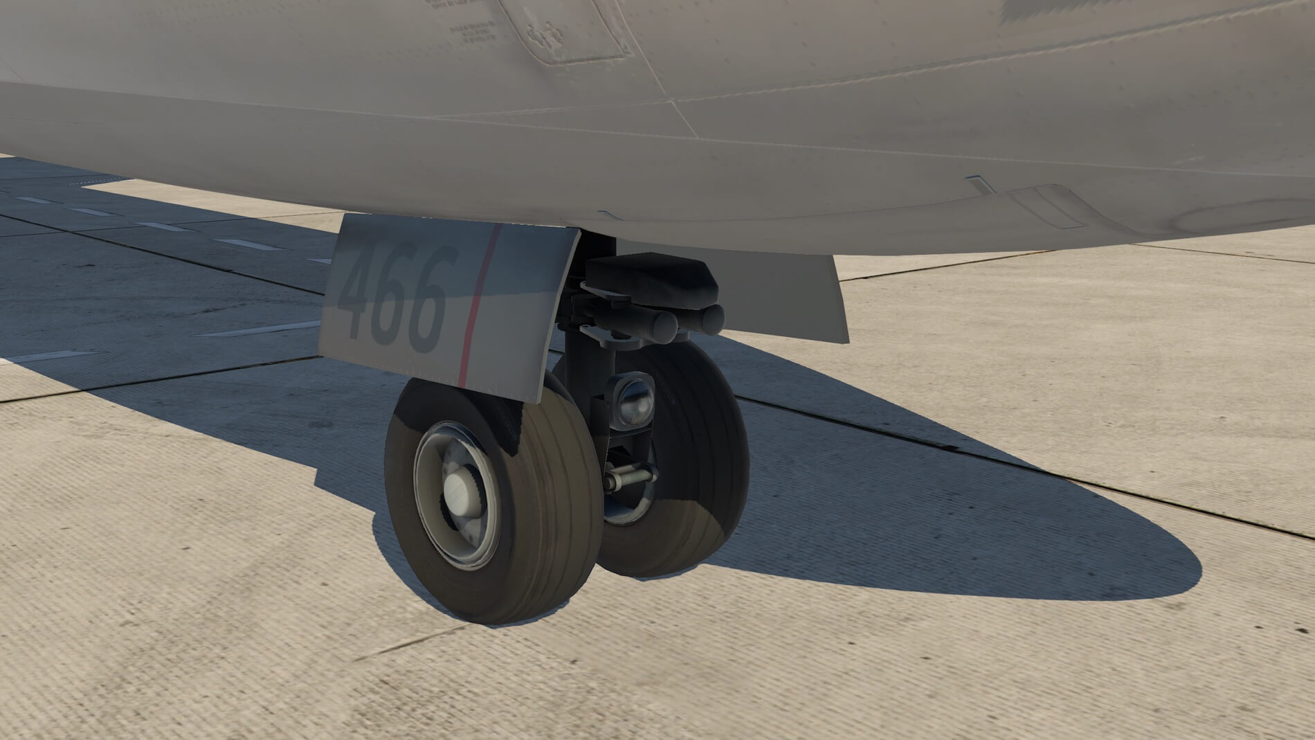
I’ve chosen the -700F FedEx stock livery and although it isn’t an inspiring painting, the livery comes with a weathered look. You can clearly see the aircraft ribs and Aluminum skin sections. Because of the NLG (Nose Landing Gear) position, it’s quite difficult to get a good view of these tiny NLG details. But with the right daylight and sun position, I can see the many tiny details that are included to make it a good-looking NLG.
I’ve got the idea that some photo real material is used …. for example, the NLG taxi light. Perhaps this is also the case with the wheel assembly, but I’m not 100 percent sure about that. The torque links at the back of the NLG look not only good, they look great. Overall, nice NLG modeling!
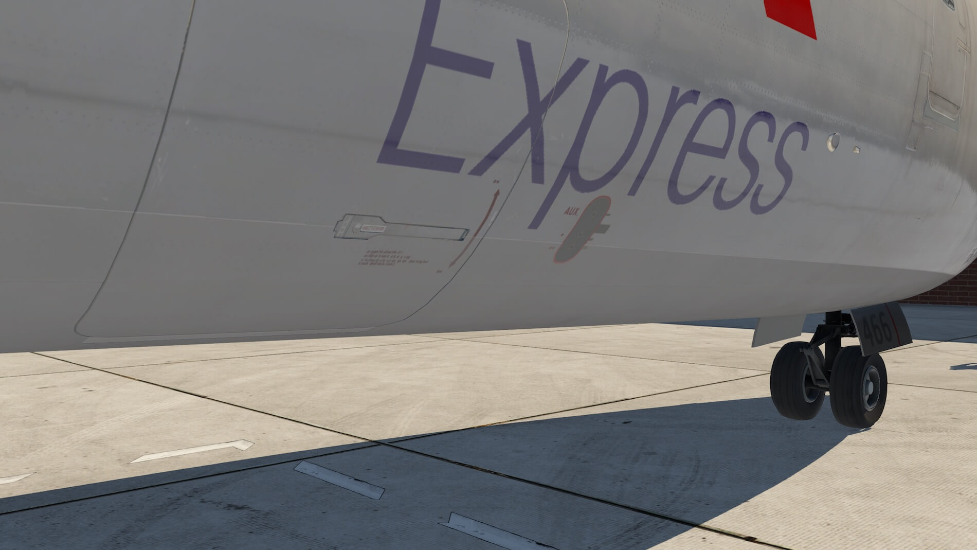
Along the left-hand side of the fuselage, you’ll pass the necessary antennas and drain masts. At the inboard section, the wing leading edge has Kruger flaps and at the outboard section, slats. Furthermore, the characteristic leading edge wing shape is clearly visible, which makes it an interestingly modeled masterpiece. While walking to the wingtip or actually it’s the fuel vent tank, I’m impressed by the simulated plastic cover that houses the strobe and navigation lights. The rear part of the wingtip offers a few static dischargers, the white aft navigation light and a fuel jettison tube.
Following the trailing edge, you’ll see the inboard and outboard flaps, but also well modeled are the outboard aileron with balance tab and the small inboard aileron with control tab. Although difficult to see from the ground, I can spot the speed brake and roll spoilers too.
But our view will be much better when I extend the inboard leading edge flaps (Kruger flaps), slats (outboard) and trailing edge flaps as well as extending the speed brakes. This gives me a total overview of the well-modeled 727 high lift devices.
They all look impressive! Even the landing light in the outboard part of the Kruger flaps is nicely modeled. And for those who want to have a look at the inboard side of the Kruger flaps, this is completely covered with photo-real material and completes the real look of these Kruger flaps.


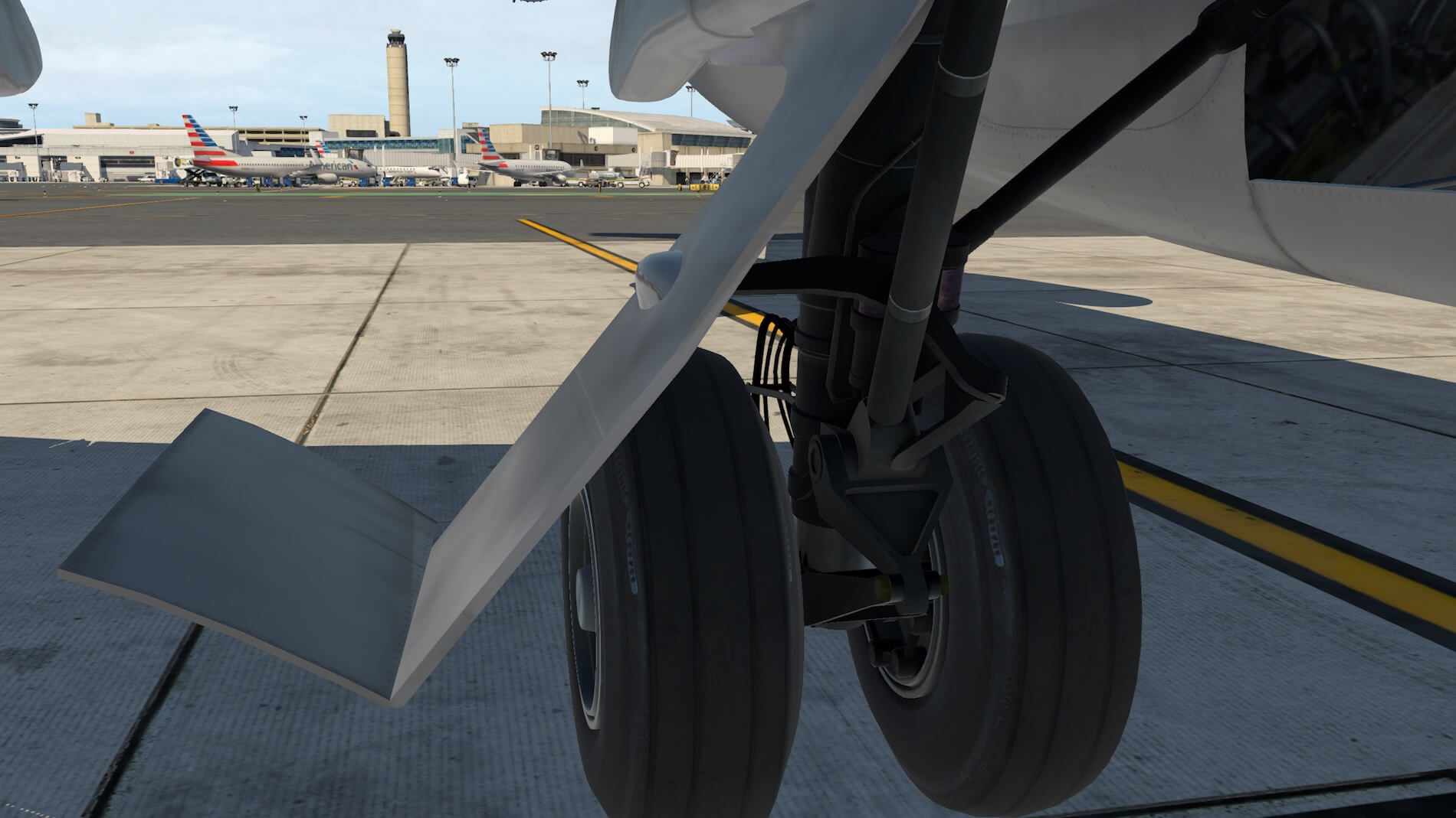
After I’ve seen most of every part of the trailing edge, I need to have a quick look at the modeling of the MLG (Main Landing Gear). Wow, that can be expressed in one word. Awesome!
The many details on the NLG, are also applicable to the MLGs. Of course, additionally, the MLG has two-wheel brake units and naturally some hydraulic lines and a skid plate at the back with a link assembly for the hydraulic lines. Overall, a well-made MLG.
The last part of my walk-around inspection deals with the fuselage tail section with the three engines. The Pratt & Whitney JT8D engines are, for those days, quite reliable. Later, the DC-9 Series and the early Boeing 737 Series will all have these Pratt & Whitney engines installed too. Although slightly different in performance, as well as the position of the thrust reverser buckets and their wing or fuselage mounting, these JT8D’s are basically the same.


Although there’s one big difference between the 737 Classic, DC-9 Classic and even the MD80 thrust reverser bucket doors versus the Boeing 727. The 727 bucket doors are mounted internally while the other aircraft have externally mounted bucket doors. When reverse thrust is selected on a 737 Classic and DC-9, you can actually see the bucket doors moving, while on the 727, you can only see them if you look through the exhaust screens.
From the ground I need to look up to see something more of the engines and the way the fuselage tail section is modeled. There’s no need for me to have my doubts about the dimensions and shape of the FlyJSim 727. The FlyJSim looks great. More than that, it looks realistic and the overall model fits with what I know about what a 727 should look like.
OK, my walk-around inspection is almost finished. I only have to inspect the other half of the aircraft before I’m back at the NLG. My overall impression is awesome. I’m really impressed about the overall quality and that means the modeling, the liveries and the many tiny details. What said before, since the 727 lies close to the ground, it’s not easy to get a good view of the NLG and MLG, but at sunset I’ve got a good chance to make some nice screenshots, as you can see!
Perhaps one item to highlight which I hope it will be implemented at a later time is the absence of animated passenger- and cargo doors and the ventral airstair at the rear of the fuselage. Also, although this is a matter of personal taste, the absence of a virtual cabin.
Before closing my walk-around inspection, some final words about the external aircraft lighting during evening, night and early morning hours. As far as I can see, all lights are operative including their reflection on the ground such as the taxi and landing lights. I couldn’t find any misaligned bulbs that are positioned outside the lamp housing.
The rotational anti-collision lights at the fuselage bottom and top are splendid. I think they’re made with the help of photo real material since they look very realistic. So, in total, on each wingtip, you’ve got three navigation lights; two green/red at the front and one white at the back. Further on, you’ll also find a strobe light in each wingtip.
Then, you’ll find, built into the fuselage near the leading edge of the wing, the WING light that illuminates the front of the wings.


And near the leading edge of the wing to fuselage joint, are the RUNWAY TURNOFF lights as well as 1 landing light. The other landing light is built in the outer leading slat section. And finally, there’s the tail light or logo light.
One last word about the pushback option.
If you need a pushback you can look for example for the freeware add-on BetterPushback which is mentioned in the manual. For those who aren’t familiar with the freeware add-on, check this out “This is a pushback plugin for the X-Plane 10 and X-Plane 11 flight simulators. It provides an overhead view to plan a pushback route and accomplishes a fully automated “hands-off” pushback, letting the user focus on aircraft startup and other pilot duties during pushback. It can of course also tow you forward, or perform any arbitrarily complicated pushback operation. To increase immersion, it speaks to you in a variety of languages and accents, simulating ground staff at various places around the world.”
More details can be found at the BetterPushback website.


The Cockpit
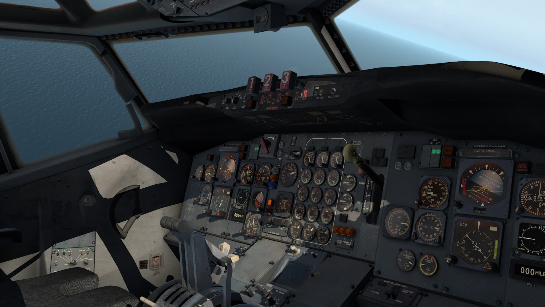
Let me first start with the 3D cockpit of the 727-200F. Over the years, I’ve seen many 3D high quality cockpits, but the FlyJSim 3D cockpit is and stays impressive. I should watch out that I’m not going to use the word awesome too many times, but perhaps it’s the best word that fits looking to this 3D cockpit.
As mentioned before, I’ve never worked on a Boeing 727 nor on a Boeing 737 although I instructed a long time ago local Italian KLM staff in Rome on the Classic 737 model and then in particular on the old fashioned JT8D engine. But still, this FlyJSim 727 cockpit feels familiar since all medium to small size Boeing aircraft of those days had the same look and feel.
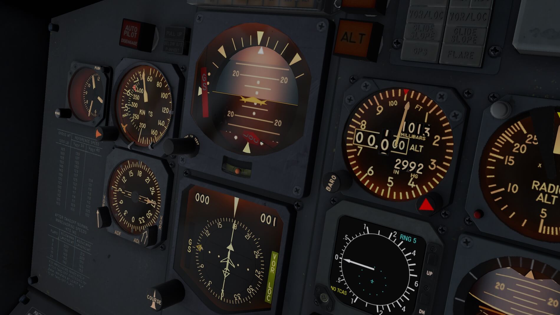
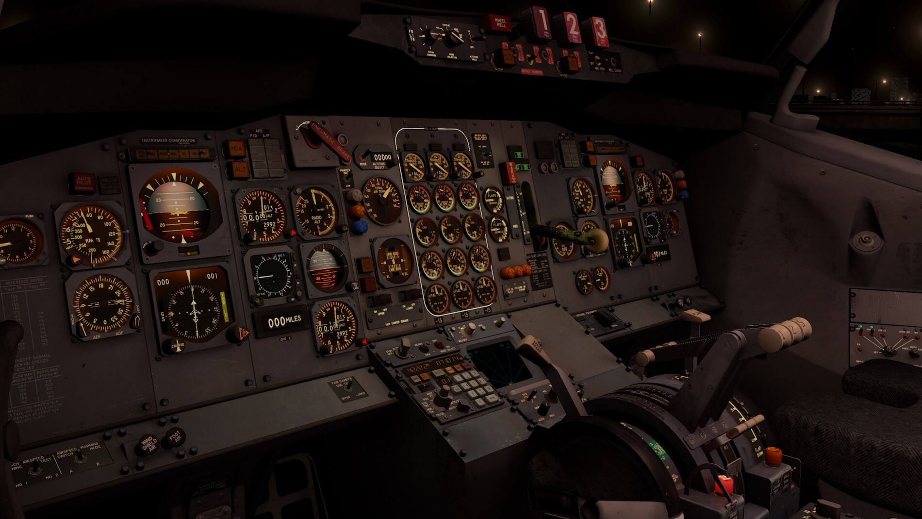
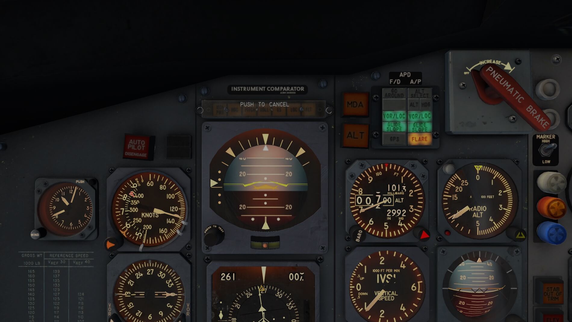
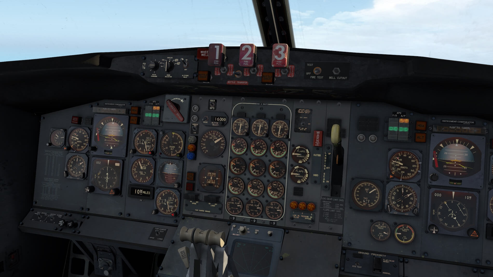
As expected, the 727 never had EFIS (Electronic Flight Instrument System), and of course also no EICAS (Engine Indicating and Crew Alerting System) and you can completely forget any FMS (Flight Management System) related systems. Instead, the 727 Classic had old-fashioned instruments, gyro’s, synchro’s and much more of those old-fashioned electrical instruments. But they had their own charm!
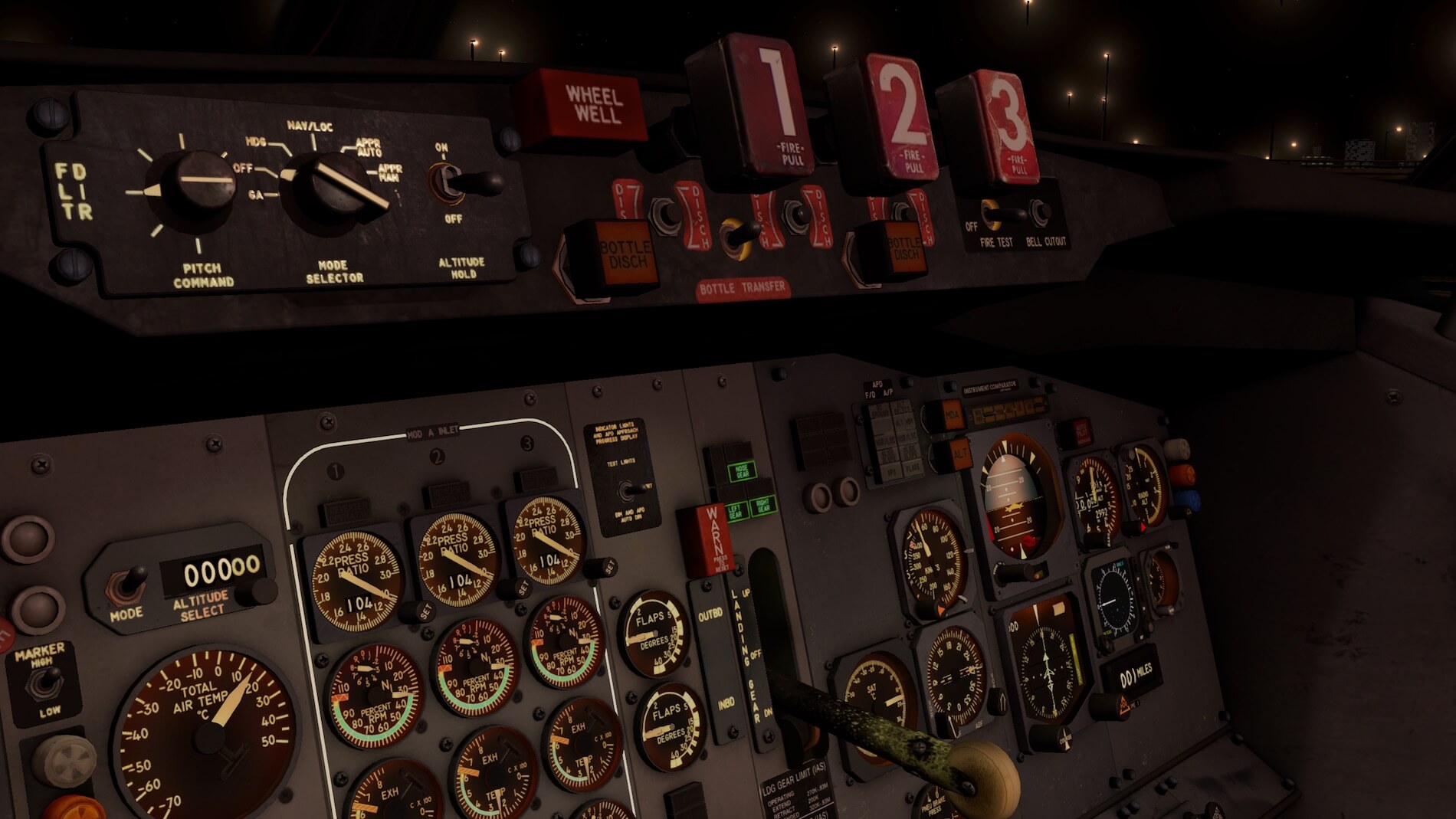
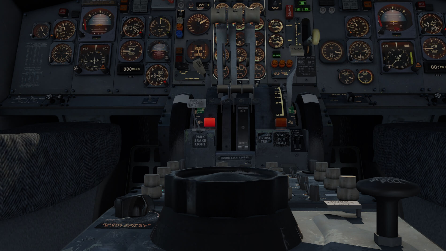
The radar screen, in the middle forward part of the center console, was in a common location in these aircraft. The location of the fire handles is unusual and for sure not common. Either the fire handles were mounted at the overhead panel or on the center instrument panel MID section. In that respect, the 727 was odd, but at the same time beloved by many pilots. Although old-fashioned, it just flies and flies and flies many more hours then you can imagine.
The way this cockpit is made, shows that the developer has a sense of high quality and who wants to extend the possibilities of 3D modeling. It’s not only the modeling of the 3D look with basic own textures, it’s the mix of photo real material mixed with handmade paintings. Honestly, I don’t know where to look first, but I think I’ve made up my mind.
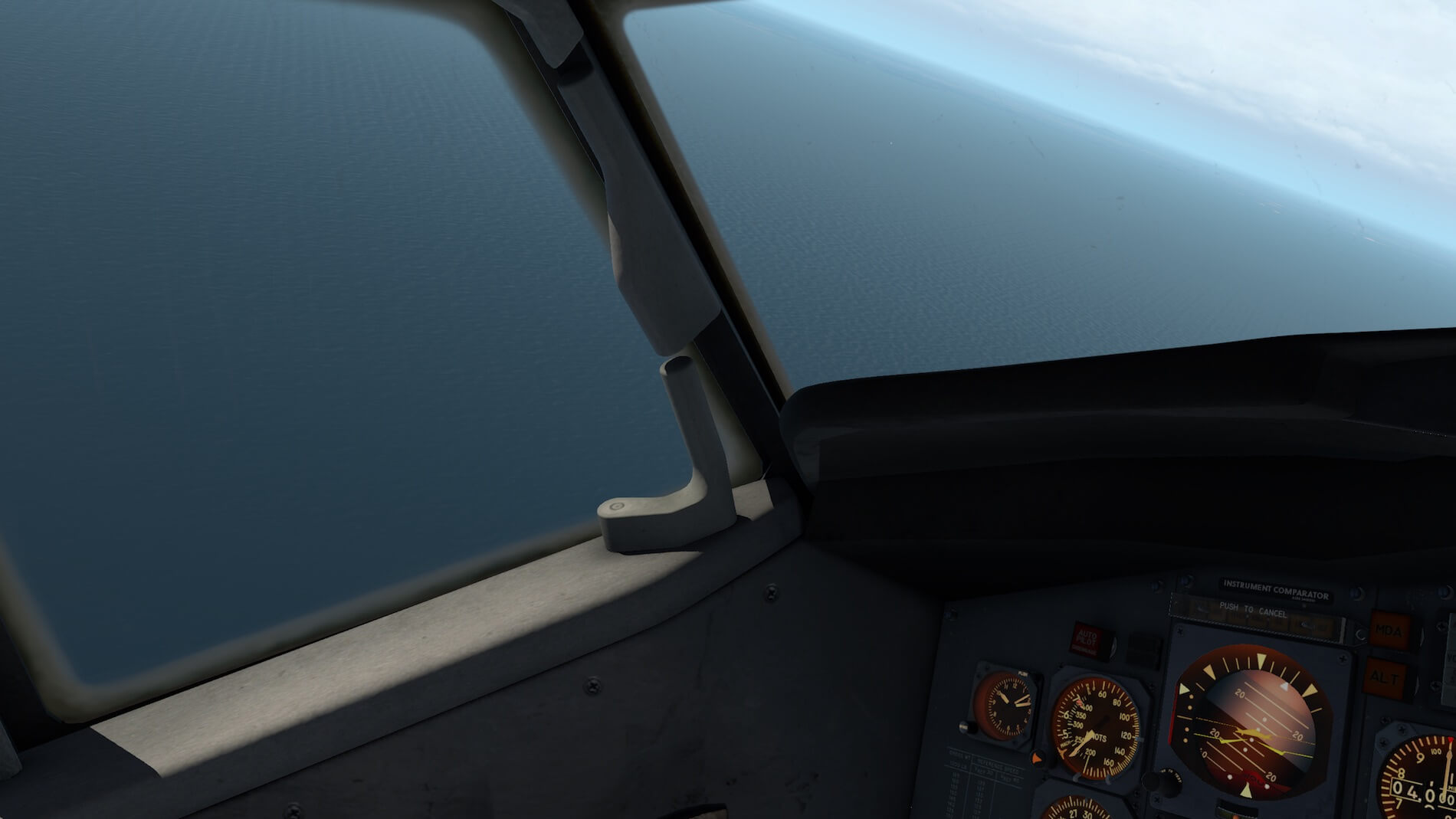
I’m starting at the Captain’s side console near the sliding window, which is, I mean the sliding window, not modeled for opening. The side panels with components, screws, decals, air outlets are all made with detail. Some decals are readable and some are not so clear, like the decal near the NWS (Nose Wheel Steering) handle.
The black glare shield topside is not just a plate. The same as with the real 727, at certain positions, it’s fixed to the aircraft structure by screws and yes, you’ll also find those screws in this FlyJSim 727.


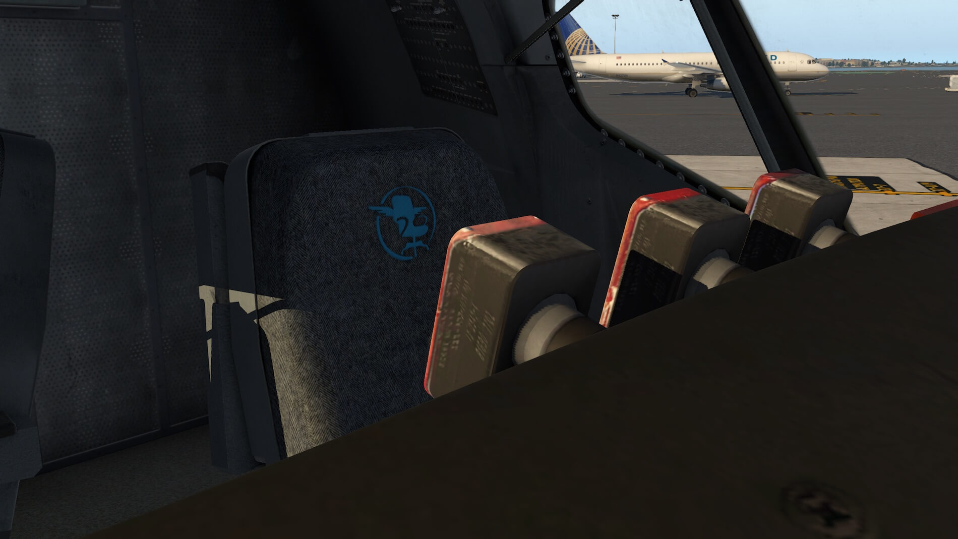

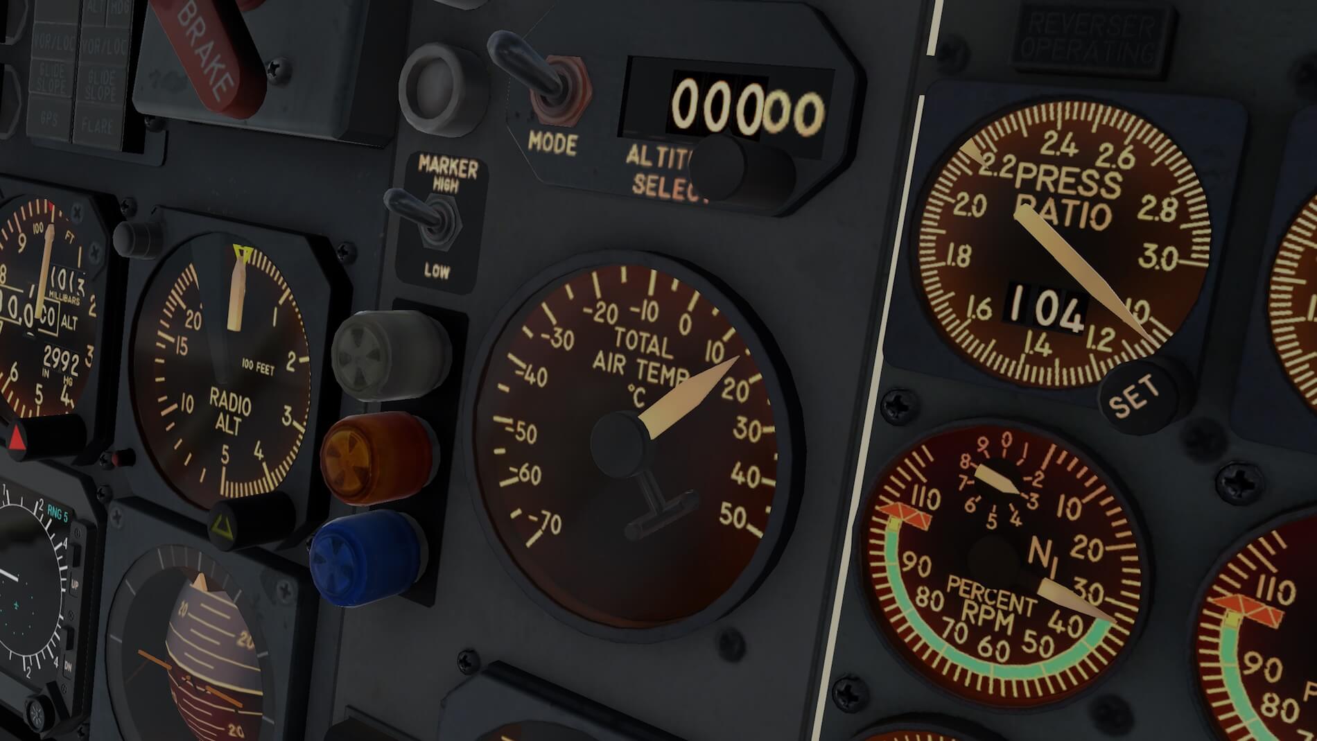
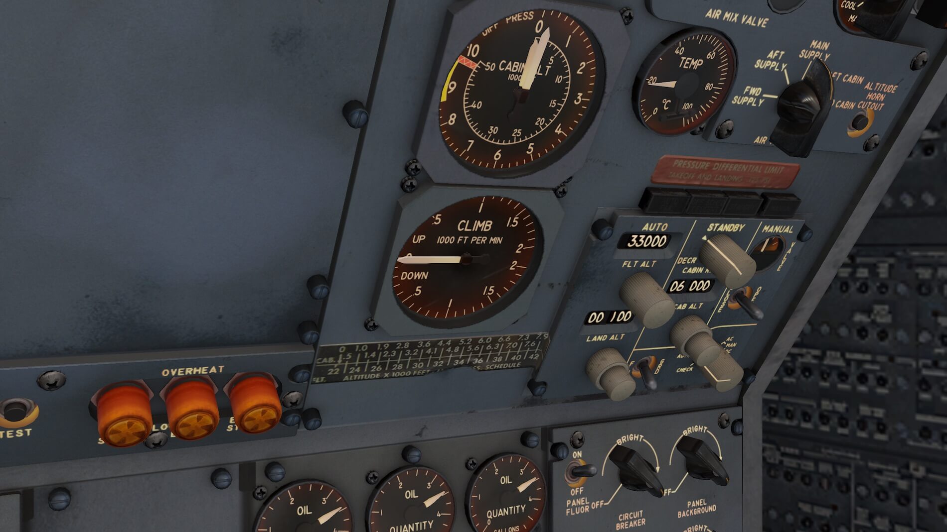
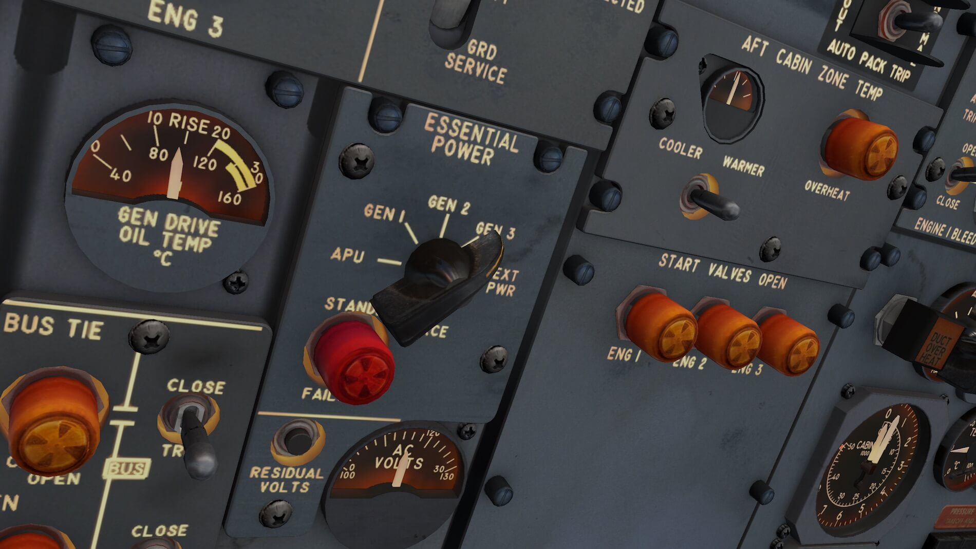
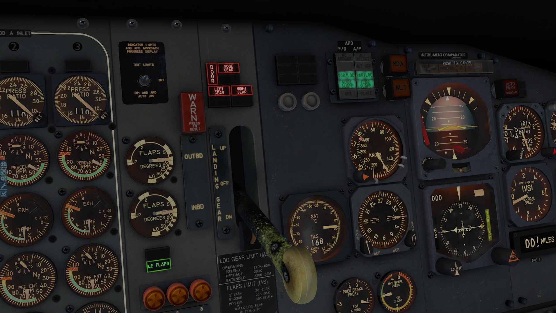
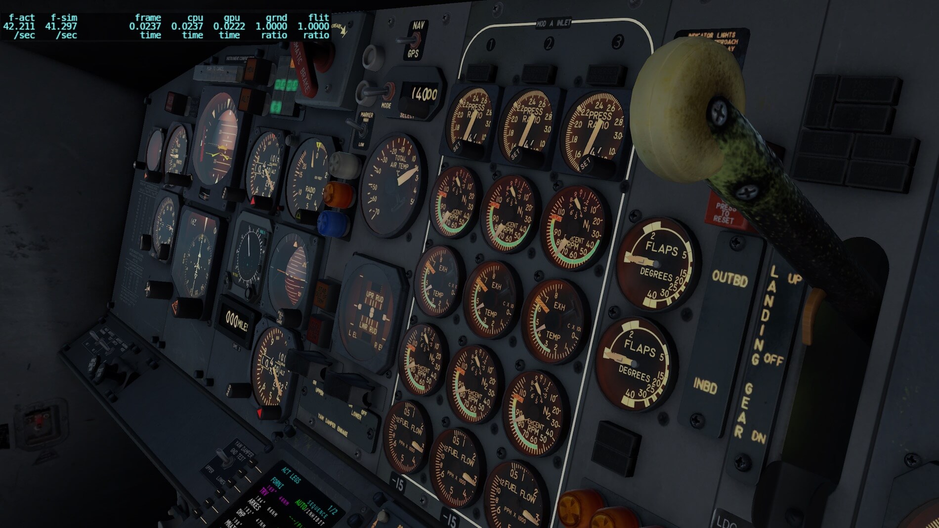
Most of the center instrument, overhead and center console panels are screwed together and therefore, you will find many of those “modeled” screws. It seems that the developer has nothing forgotten. But then, how is the quality of the instruments? The 3D effect of each instrument/indicator is clearly visible, as well as is the needle or needles, the indicator plate itself with markings and when applicable, the knob or switch to make a certain setting.
The instruments, even on the FE panel (Flight Engineer), are sharp from a distance, but it stays sharp even when you zoom in, but it doesn’t stop here. The switches, lamp units, knobs, annunciators, it all look so real. The only thing that is missing, is the typical cockpit smell!
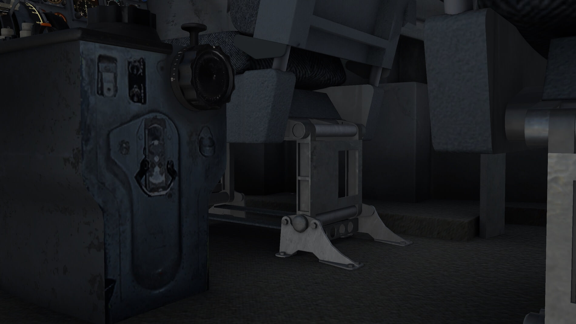
And yes, it sounds boring, but FlyJSim made a realistic 3D cockpit with weathered panels and/or components e.g. the landing gear handle.


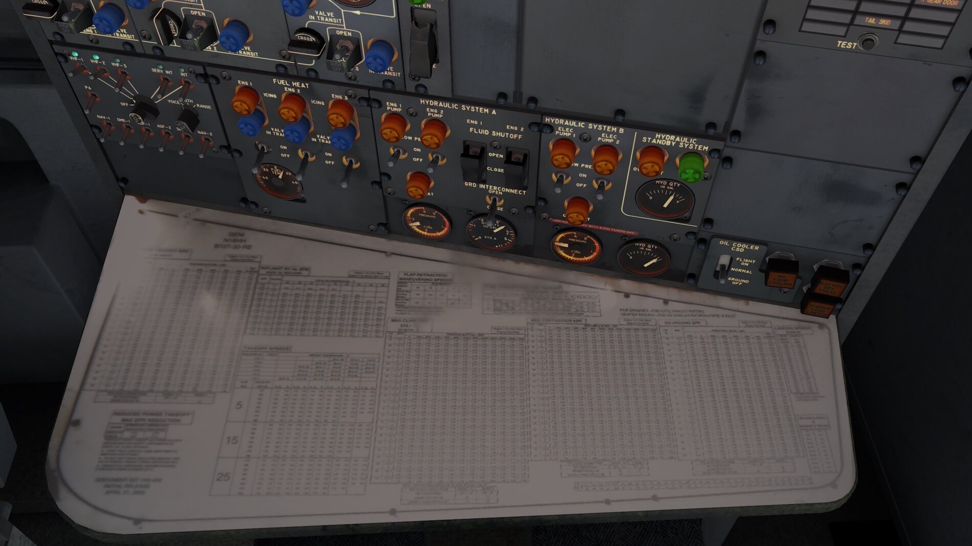
But, I think there’s also a need to highlight the FE (Flight Engineer) area.
The FE table is covered with different performance tables like those needed for aircraft speeds and engine performances. Although you can’t read them, the idea is great and it gives this FE cockpit position a realistic look. All the sub panels together give this FE panel an “as real as it gets” look. From a certain distance, it looks good, but even in a close-up situation, it still looks awesome. If you zoom in, you can read every word or value written on the sub-panels.
Likewise, the switches are nicely modeled as well as the round indicator lights. These lamp units allow you, by rotating them, to dim the light intensity. This was a very common lamp unit for those days.
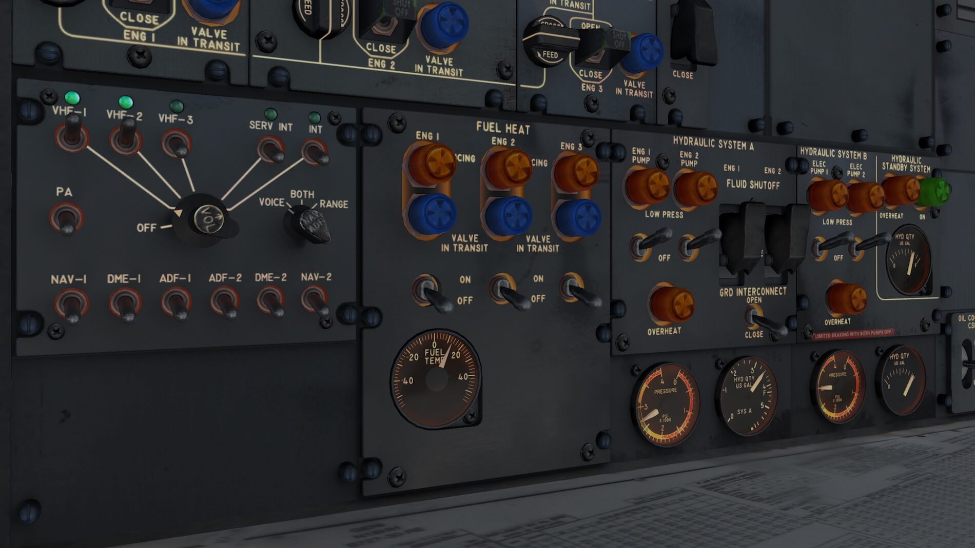
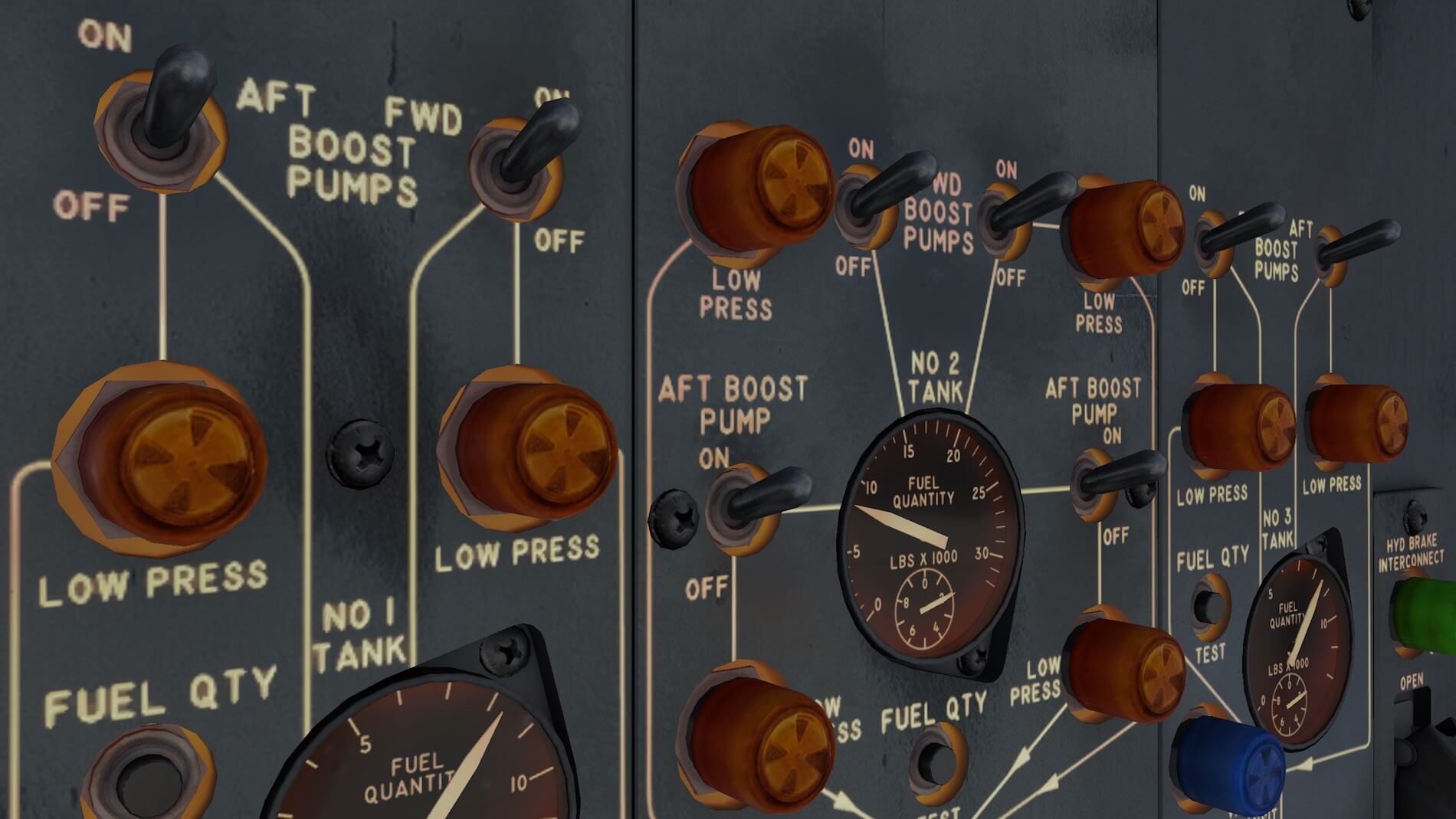

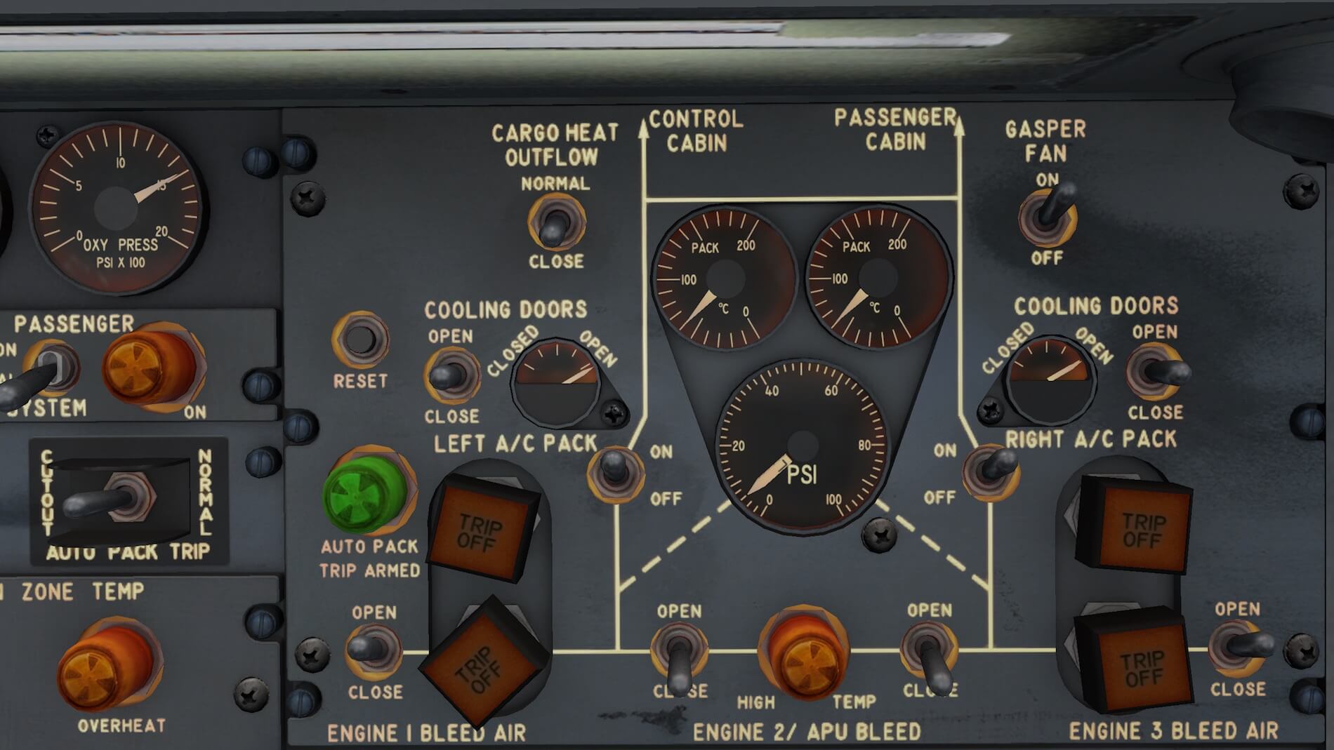
While sitting in the FE seat, and turning yourself 90 degrees to the right, in the direction of the cabin, you’ll find another small AUX POWER UNIT panel on the side panel, just above the position of the leading and trailing edge light devices. And above that, there’s a fuel panel with blue lights and switches.
Last, but not least, is the overhead panel.
Compared to today’s modern jets, the overhead panel looks empty. But those panels that are simulated look OK to me and come with the same quality as seen before. Some 727 sub-panels are, on today’s jets, no longer situated at the overhead panel like the ATC and the AUTO-BRAKES panel.
Most of the time these panels are installed on the pedestal. Anyway, the overhead panel follows the same quality as all other pilot panels as well as the FE panel. Although not simulated and not of much interest, the C/B (Circuit Breaker) panel right of the FE isn’t modeled at all. The wall is covered with photo real C/B image textures, but it’s not readable at all.


Overall, this is a well-designed, nicely modeled 3D cockpit with an eye for all the tiny details. It’s obviously been created with a lot of passion! In the next section it’s time to check out how all systems work and to find out the flight characteristics. As far as I can see, and not confirmed in the Systems manual, all cockpits and systems of the -200 Advanced and -200F are the same, but remember that each of the aircraft versions will have different performance values.
Same as I did with my walk-around inspection, how’s the 727-cockpit night lighting? I can be short with this …. the night lighting system is gorgeous. You’ve got so many light selectors that you hardly know which gives what and where. Just to give you an idea what’s possible, you have MAP, LEFT FWD & SIDE panel, CENTER FWD panel, FWD panel background, FWD panel fluor, overhead panel, control stand (pedestal) RED, WHITE, RIGHT FWD & SIDE panel, DOME WHITE and a LIGHT OVERRIDE switch.

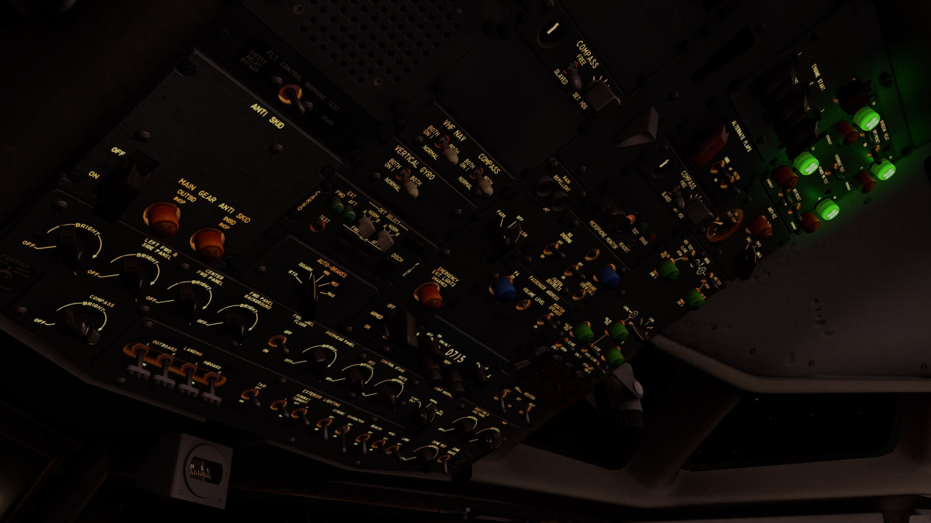
I think there’s enough choice for you to find the most convenient lighting condition for you during your night flights.
Oops, almost forgotten .. the Virtual Cabin.
I can be short with that. The 727 doesn’t come with a virtual cabin. A pity or not? The final decision lies with the developer to add a cabin or not. Reasons “not” to add a virtual cabin could be reduced frame rates, too many polygons used for something that’s probably not too often used by simmers and too much time to spend in creating a cabin while work on the cockpit has a much higher priority. So, no virtual cabin. We must life with this!
First Flight Impression
Without too many preparations, except for the checklist items, I decided to see how this 727-200F taxies and flies from, yes, again, KBOS. I load my aircraft full with fuel, no cargo on-board while the digital takeoff data-card shows the speeds and later, I need to find out if this 727 flies as realistically as possible.
Although I’m a holder of an FAA PPL (Private Pilot License), that’s still no Boeing 727. Therefore, it’s very difficult for me to find out if these commercial jets fly as realistically as possible. Taxiing isn’t a complicated issue, since I’ve taxied as a ground engineer in the third seat, so I can recognize if something feels OK or not!
I decided to take a long taxi route to runway 27 KBOS that gives me enough time to feel, hear and to control the 727 along the centerline of the taxi way. The result was surprising. Steering works perfectly using my Saitek X52 Pro, but the 727 doesn’t respond immediately, so low taxi speeds are mandatory otherwise you can’t make a nice turn.
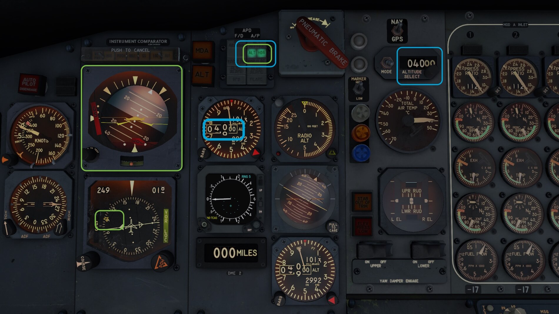
Once aligned with the runway, I perform the last checklist items and there I go, throttles full forward. The 727 accelerates slowly and honestly, it feels good. It feels realistic. And then there’s also no need to worry about at which speeds you need to do something, since the digital data-card calls for 80 knots, V1 and VR. In other words, everything is covered for a successful takeoff. I have on purpose disabled my co-pilot for all the announcements, but perhaps it was better to leave it on. He, or is it a she, will warn me I assume for things I need to do or things I forget. Anyway, I take off from 27, climb out to an initial altitude of 4000 feet following runway heading.


It’s because I can remember and that I reviewed the FJS 727 v2 Study, it’s absolutely needed that you and I need to read how to operate and understand the FD (Flight Director) and AP. It’s not really a basic AP, it’s a bit more, but the fact that on the glareshield you’ve got the FD controls while on the pedestal you’ve got the AP panel, makes it perhaps a bit confusing for others. And before I forget it, this aircraft doesn’t has Auto Throttle or Auto Thrust. That said, when you’re busy alone in the flight deck with controlling the aircraft for pitch, roll and yaw, don’t forget that you also need to monitor in-between all that other work like the IAS.
What I personally miss it a popup for both the FD and AP panels. Ok, the FD panel on the glareshield could be left as it is, but a popup of the pedestal mounted AP controls would be very helpful. I know, it’s not as real as it gets, but flying a 727 alone in the flight deck isn’t reality either, so hopefully Jack from FJS understand what I mean and feels too that such a popup window is handy.
Once airborne, I’ll try to keep a certain pitch, retract the gear and slowly, the flaps. At 4,000 feet, here we go once more …. I decide to connect the Auto Pilot (AP) via the ENGAGE lever. With the MODE selector in PITCH HOLD, the current A/C pitch is maintained. A little while later, I change to a certain Vertical Speed and to achieve this, I set the MODE selector to V/S and adjust my actual aircraft V/S with the thumbwheel.
If needed, you can use the TURN button to adjust your heading. This is what I call a basic AP. No pre-settings at all. Difficult? It’s very easy and is high technology for those days. I disengage the SERVO lever which disconnects the AP and fly further by hand. It’s an easy aircraft to fly, I must say. A small correction is needed regarding the “no pre-settings at all”. You can set a preselected altitude on the main instrument panel.
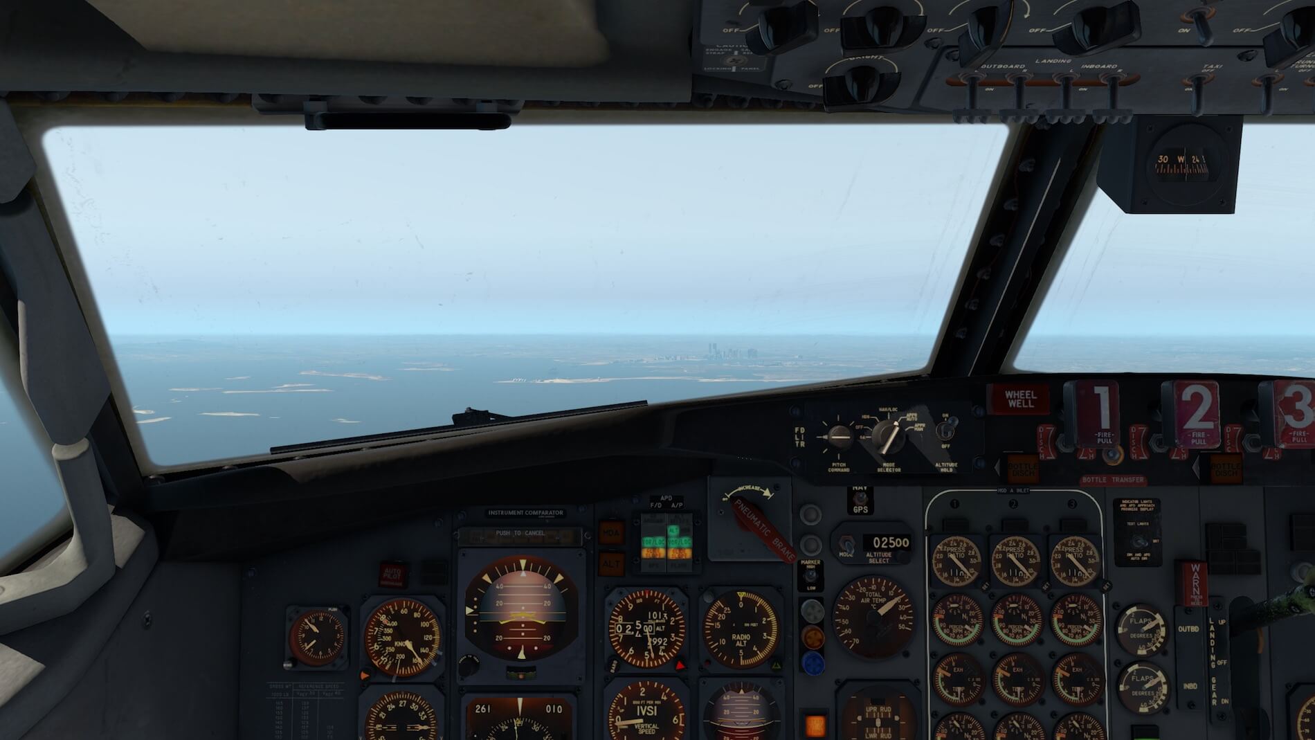
Keeping the aircraft with pitch and roll trim at 4,000 feet, I decide to return to the airport and for the moment it doesn’t matter which airport it is if I can land with the 727. After base leg, I turn to final, descent to 3,000 feet and make the necessary preparations for my final approach back to KBOS. And don’t forget to check the landing data-card information. The 727 isn’t the size of a 777, 747-400, A380 and it almost flies like a large GA aircraft.


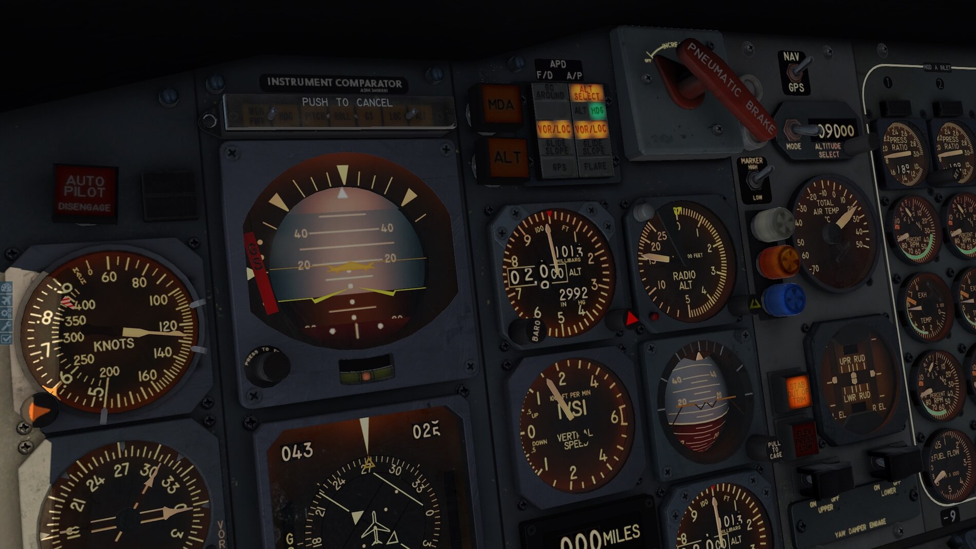
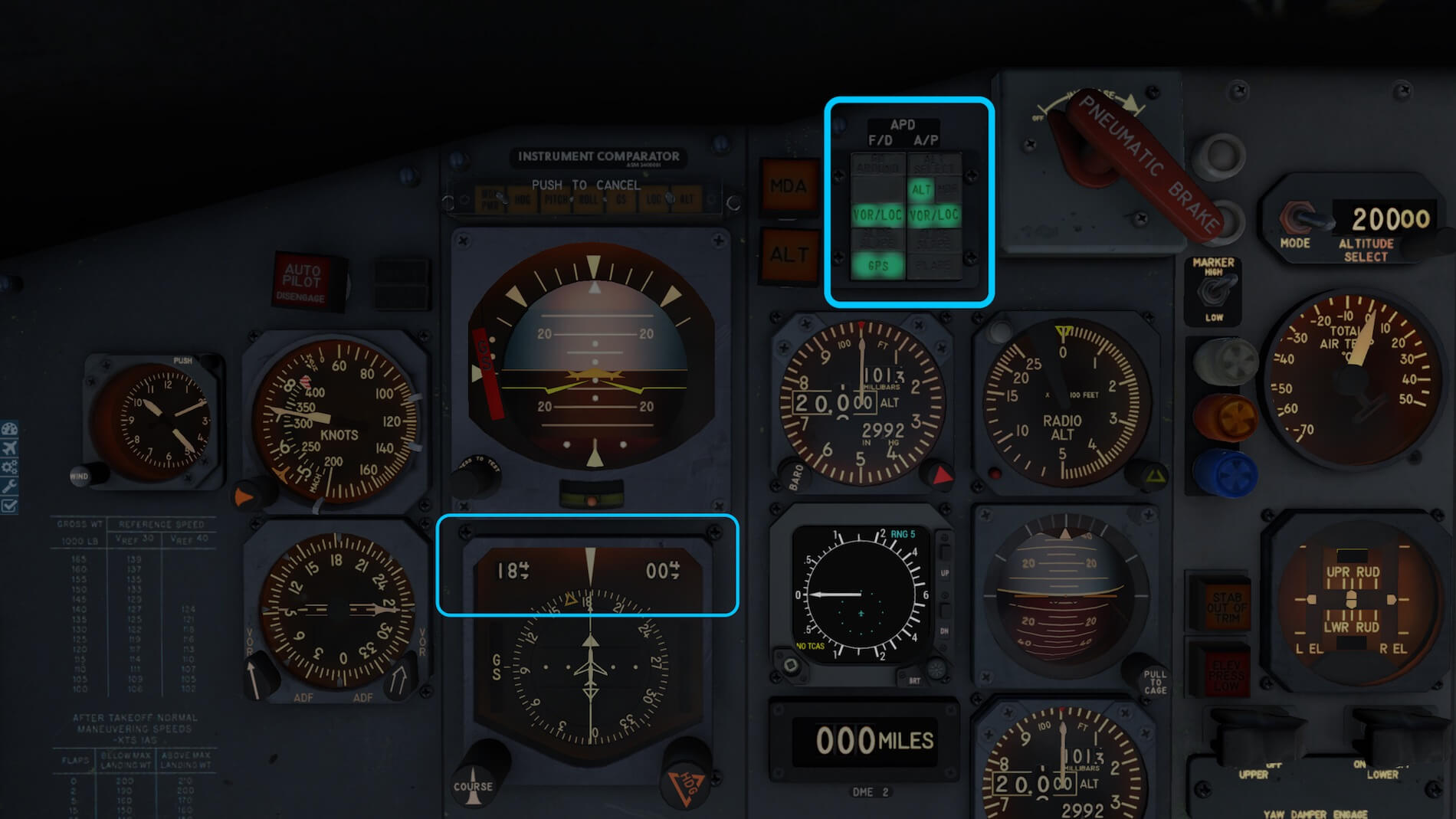
The pitch, roll and yaw movements feel OK and whenever you decide to change your roll, the aircraft moves slowly from its current stable flight to a new flight position in a way a real 727 should do. But what when you want to use the AP in combination with the FD. After I entered for the intended runway the ILS frequency, you need to tell the AP and FD what you want thus an automatic approach, right? When you look closely to the AP/FD annunciator panels in front of the captain and co-pilot, you see that the left-hand half gives FD information and the right-hand side the AP information.
You set the FD MODE SELECTOR on the glareshield panel to APPR AUTO and on the AP panel (pedestal) the NAV SELECTOR to AUTO G/S. When I have done it all right, I will see when approaching runway 27 KBOS, that the amber VOR/LOC indications on the F/D and AP annunciator turns green. That means, it’s captured. Both for F/D and AP GLIDE SLOPE are still amber for the simple reason that I’m still way too far out to pick up the G/S signal.
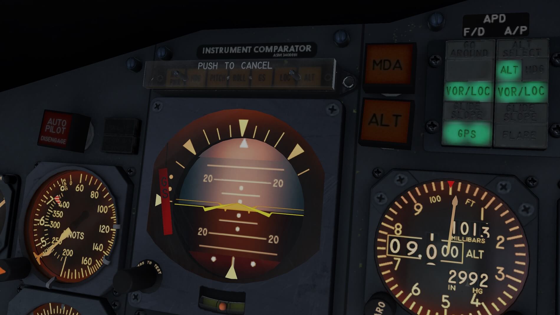
After a while the glide slope signal is detected and before I know, the amber lights turn to green on the annunciator light panel. And I say it again, keep monitoring your IAS and double check with the LANDING data card. Further on, there’s no ECAM or other sophisticated system that tells you when you extend your flaps and gear, so you should do it yourself.


I had seen it before, and I can confirm that it works ….. the implemented AP has a FLARE function, so that saves a lot of work on landing although I found the flare a bit slow in response. But FLARE may be implemented, you still need to control the engine reverses and to manually brake unless you had set a certain Auto Brake. By the way, when you’re also flying the modern big jets like the SSG Boeing 747-8, the ToLiss A319, the JARDesign A330 or the Flight Factor A320, keep in mind that those fan thrust reversers are much more powerful then the ones mounted on these JT8D engines. You can rely on them, but the “deceleration” effect is not that high as with these modern hi-bypass engines.
All together, making a manual approach is rather easy and realistic although the 727 is still a medium size aircraft. I was at least, impressed about the flight dynamics and besides that, the way the aircraft is modeled and behaves although I’ve got no reference with the real 727 jet.
Second Flight Impression (Using VOR / VORTAC)
My short test flight will be from LFBO (Toulouse – Blagnac Airport) to LFMN (Nice Côte d’Azur Airport), both located in France. For this flight I use the old-fashioned way with the help of VOR stations, whatever is available or applicable and this means I need to enter each new frequency of the next station. I could also use instead of VOR, NDB stations, but if I can find VOR/DME, I prefer those navigation aids. Yes, it’s a completely different way of navigation than in today’s aircraft with company routes and using FMS (Flight Management Systems).
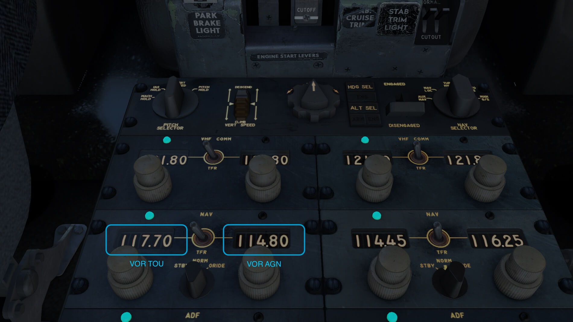
OK, I made my flight plan myself. That said, I’m not using for this typical flight RouteFinder (http://rfinder.asalink.net/free/) nor the onboard FMS MCDU. This means, I leave the pedestal left-hand front position empty. That said, I’ll fly following these VOR stations: LFBO (runway 32L) – TOU (117.70) – AGN (114.80) – GAI (115.80) – PPG (116.25) – FJR (114.45) – ITS (112.70) – MTG (117.30) – MRM (108.80) – LUC (113.00) – CNM (111.40) –LFMN (ILS 04L (109.95 / 044)
Although not a real flight plan, the idea is to see how the 727 follows VOR stations and to see if I can make a good ILS landing.
With the help of the FlyJSim checklist and having a quick consider the start up from a “cold and dark situation” video, I think it’s quite easy to follow all the necessary steps. Since the systems are quite well simulated, you get a good idea what’s going on. My first VOR station is TOU, followed by GAI. I’ve already entered these in the active and standby windows of NAV set 1. That said, you need to enter every time a new VOR beacon frequency in the NAV panel. Yes, I’m aware that this is a lot more work then when you own an FMS MCDU, but it’s the reality how it was done in those days when no FMS existed.
I’ve decided to take 6,000 kilograms of fuel, which should be enough. And sorry, there’s no fuel calculator or at least, not that I know of. I double-check the build in weight and balance panel as well as my V speeds. With my current aircraft configuration, I have on my V card calculator a V1 of 115, VR of 115 and V2 of 127. Don’t worry … you’re warned, during the takeoff run, when you reach 80 knots, V1 and VR. And remember, these figures could differ with yours.
During taxiing, you have to keep in mind that your taxi speed is not too high, otherwise making a left or right-hand turn isn’t easy since it doesn’t respond that quickly. While flying manually, the pitch, roll and yaw changes take some moments. No, not minutes to respond, but for sure some seconds. Same as with large aircraft!
Since default X-Plane 11 Toulouse/Blagnac isn’t really modeled, I believe I’m somewhere at the old Airbus factory at the other side of the actual Blagnac airport. Therefore, taxiing to runway 32L is a short distance. After warming up my engines for at least 5 minutes, it’s time to taxi and make a rolling takeoff. A very interesting feature we also see with this FlyJSim 727 is that during the takeoff you will hear a rumbling noise, in this case of the runway. Most of the time this is caused by the runway center line with the integrated center lights.
My takeoff, the initial climb, followed by further climbing till and including the cruise works fine for me. After I retracted the GEAR and FLAPS, I decided to keep on flying by hand. No Auto Pilot engaged, just trimming the aircraft and flying by hand. This gives me such a good feeling. An aircraft that’s big enough to fly by hand, trimming so it feels like a GA aircraft, easy on going, but at the same time it takes time before a trim change becomes visible.


When you want to use the basic AP, go ahead. It will work flawlessly, but you won’t feel how it flies. And yes, I mentioned “basic AP”. A basic AP was common for those days, I said that before. You don’t have complex digital Auto Pilot computer nor that the aircraft was fitted with an Auto Flight system.
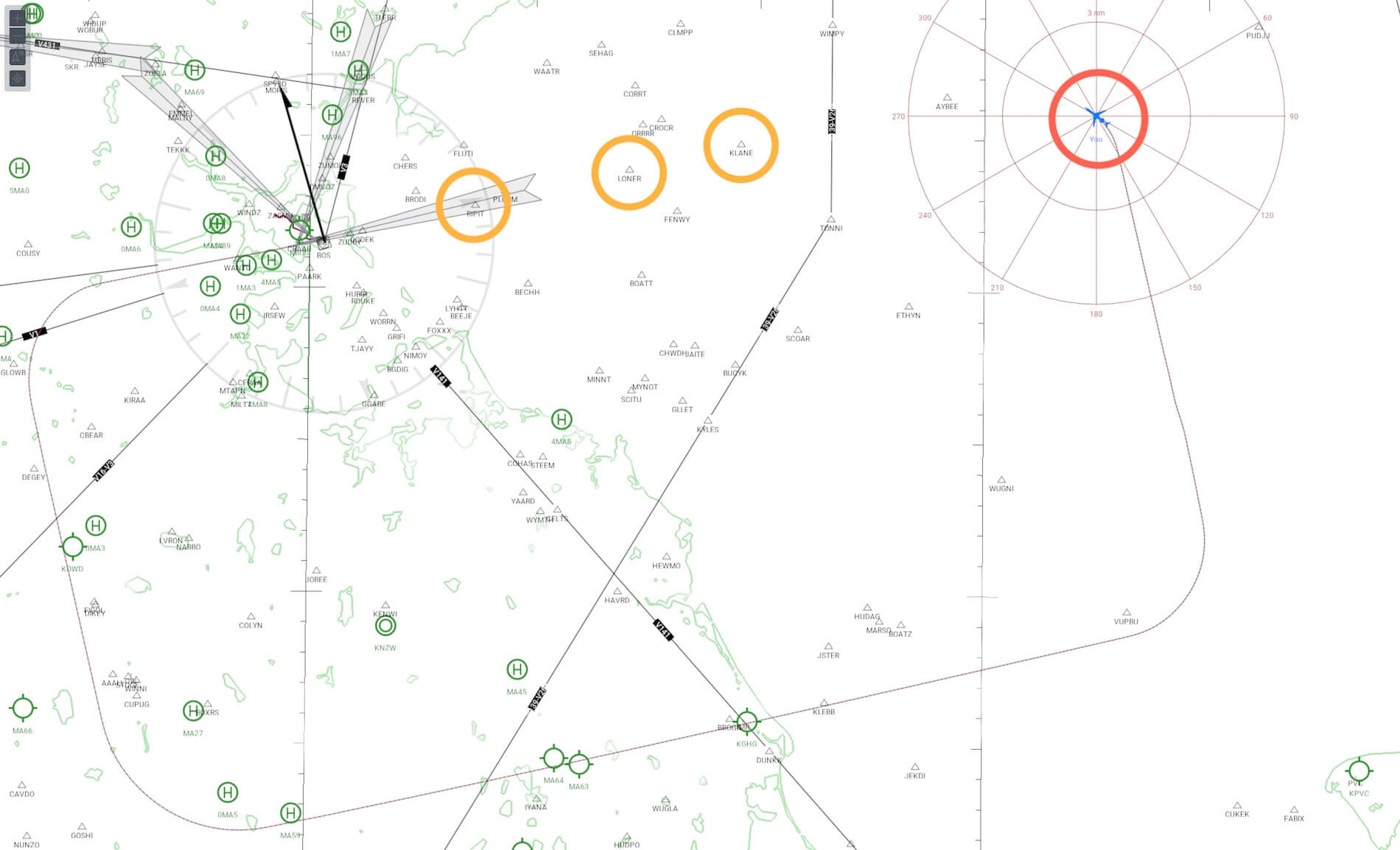
Flying from VOR to VOR is nice, but unfortunately not every VOR station I had selected had a DME. Not a problem, but then you need to check the HSI constantly and watch for the moment that the TO-FROM indication/pointer changes. Some stations along the chosen route did have DME, and that makes life much easier. Let say 5 to 4NM before you fly over the VOR/DME station, you switch to the other VOR station and move on.
Using the VOR to VOR flight with the AP engaged and in action, is fun. It will most likely take some time you understand how the AP works, even after you’ve read the dedicated manual pages. When the VOR has no DME signal, then there’s not really a problem except that when you use no additional map, you wait till the needle moves out of the middle and the TO pointer turns to the opposite direction. This means, you’ve passed the VOR beacon. Time to select on the NAV panel the next VOR frequency.


Flying VOR to VOR station isn’t so spectacular. You only need to monitor what you’re doing, where you’re flying to, the DME to go, and of course you need to monitor and/or adjust the IAS and so on.
But even this funny flight is reaching the end. At VOR station MRM I decided to start my decent just by trimming the aircraft. Using the AP is something I did in my previous flight, so I like it this way. The planned VOR station LUC and CNM are more a help and not a need. Somewhere between 10-20NM before LUC, I decide to prepare myself for a lading on LFMN ILS runway 4L.
Frequency and runway heading are set, approaching at 4,000 feet per the papers and here we go. The ILS or LOC (localizer) is picked up as expected and at approximately 12NM the glide slope is picked up too. The 727 is descending along the ILS GS path, and I have, lucky for me, the runway in sight. Once more a double-check on the landing data and I’m ready for it.
Without Auto throttle it takes some more effort to get the correct speeds, but I manage it and the 727 does too. Before I know it, the 727 has landed although I have to admit that before the actual landing I decided to make my own flare and landing. Why not? To complete this short French flight, I need to taxi to a place at the apron.


What my overall impression?
It’s a great aircraft to fly!
According to FlyJSim, real licensed ATPL 727 pilots tested this 727 Series, and I think Jack did a great job. If the 727 behaves realistically is something I don’t know with only a frozen PPL in my hand, but looking at the aircraft’s ground and flight behavior, I think that it reacts as a real medium to large aircraft.
I made several VOR controlled flights, but I’m not 100 percent satisfied about the VOR capturing. Once it flies and that it has correctly captured a VOR beacon, it goes well, but I also noticed that when switching between VOR stations, the aircraft is not always doing this straight. Either it makes the wrong turn or I feel it’s better to set it in HDG mode for a while and that it gets the chance to capture a VOR which is visible on the RMI and then see what happens before moving back to VOR/LOC mode.
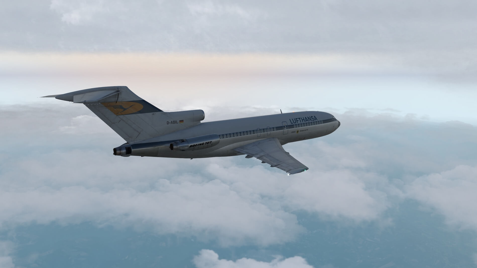
Some words about the old-fashioned Lufthansa 1965 livery. This is just one example of liveries for this FJS 727 v3, painted by Atarium. All his FJS 727 v3 liveries can be found at our Download – Liveries – Atarium (FlyJSim).
Third Flight Impression (Using FMS)
Introduction
Before starting with this third flight, some words about the installed FMS MCDU. Since I’m not really familiar with real 727 retrofit packages, I consulted FlyJSim to help me and you a bit with an installed FMS MCDU. According to Jack “a lot of 727s were retrofitted with all kinds of GPS/FMSs, ranging from the simple Garmin GPS to full on Boeing FMCs. The 727s really were a hog pog of options!”
Flight Plan Creation
To create a flight plan you could use many programs like Routefinder which offers you quickly a flight plan, but this is not in “X-Plane fms” format. Or you could go for FlightAware, but again, this doesn’t allow you to export it to an fms file format. Another option simBrief. You need to register but it’s for free and a wealth of flight planning information becomes available.
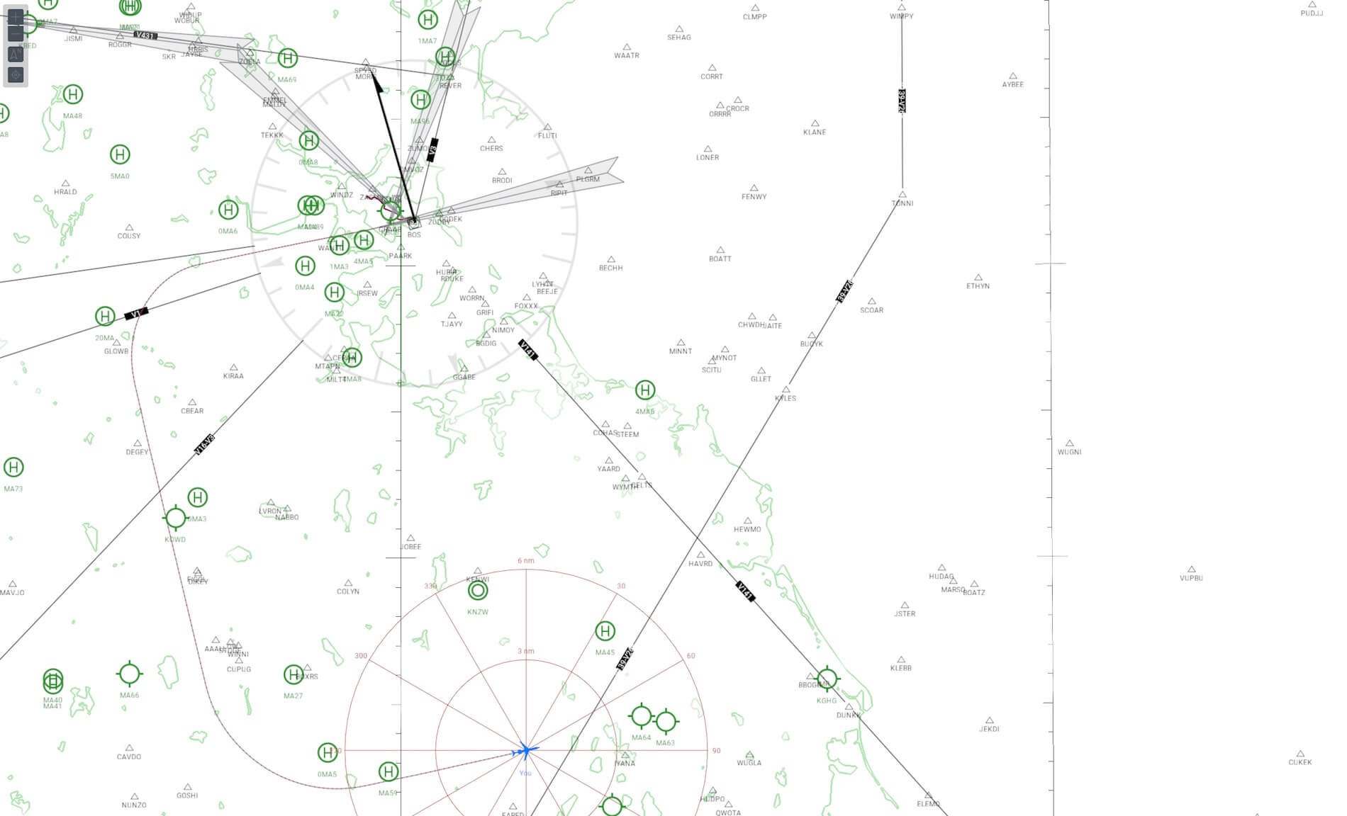
Then there’s also the browser-based Online Flight Planner, but I go for SkyVector, but I need for this X-PlaneTools. You and I all know SkyVector, but SkyVector saves your flight plan in fpl format which in turn can be converted to fms with X-PlaneTools. I prefer to create a sightseeing IFR flight, so I use SkyVector above all the other options since it allows me to add waypoints on my scenic IFR route. One of the reasons to use SkyVector is that you’re free in the waypoints you want to use.
And finally, there’s also a freeware program that’s called Little Navmap. It’s a great program, works flawless, using real AIRAC data and offers so many possibilities. Right now, of this writing, this is my preferred flight plan programming tool and the other good news is that it’s for Windows, macOS and Linux. Want to know more about it; check out this dedicated URL.
Since the FJS 727 uses the default FMS MCDU from Laminar Research, it uses flight plans with the “fms” extension and that’s good news since it’s widely accepted as format thus many flight planning programs do offer this extension. Added to this; where to install your created flight plan? Simple …. in the Output/FMS plans folder.
My KDAB to KEYW Flight
Hold on, from where to where are we going?
That a good question …. and an easy answer …. the flight goes from Daytona Beach International (KDAB) to Key West International (KEYW) which means, we’re in Florida and flying to the Keys.
Although this flight is at a different location then the one in France (Europe), it’s basically of the same setup except that we use and load a flight plan in the on-board FMS MCDU. As you might know, there’s no longer a need to enter the necessary VOR frequencies. Instead, we load the flight plan which consist of a couple of VOR beacons but mostly out of waypoints thus latitude/longitude coordinates.
Will this be difficult?
Will it be a different flight then before in respect to the FD and AP?
Will it lead to a higher workload?
Will it ….. and so on!
Except for the workload question, which will be less then using VOR beacons only, all others result in a more or less same flight. Using the FD with AP is not much different, flying the aircraft is also the same in case we fly it manually and trim it. That said, I’ll try to write down only these things that make this third flight special. All other aircraft conditions and behavior are the same unless I have thunderstorms along the route to the Keys.
Among other things, what is new to this flight?
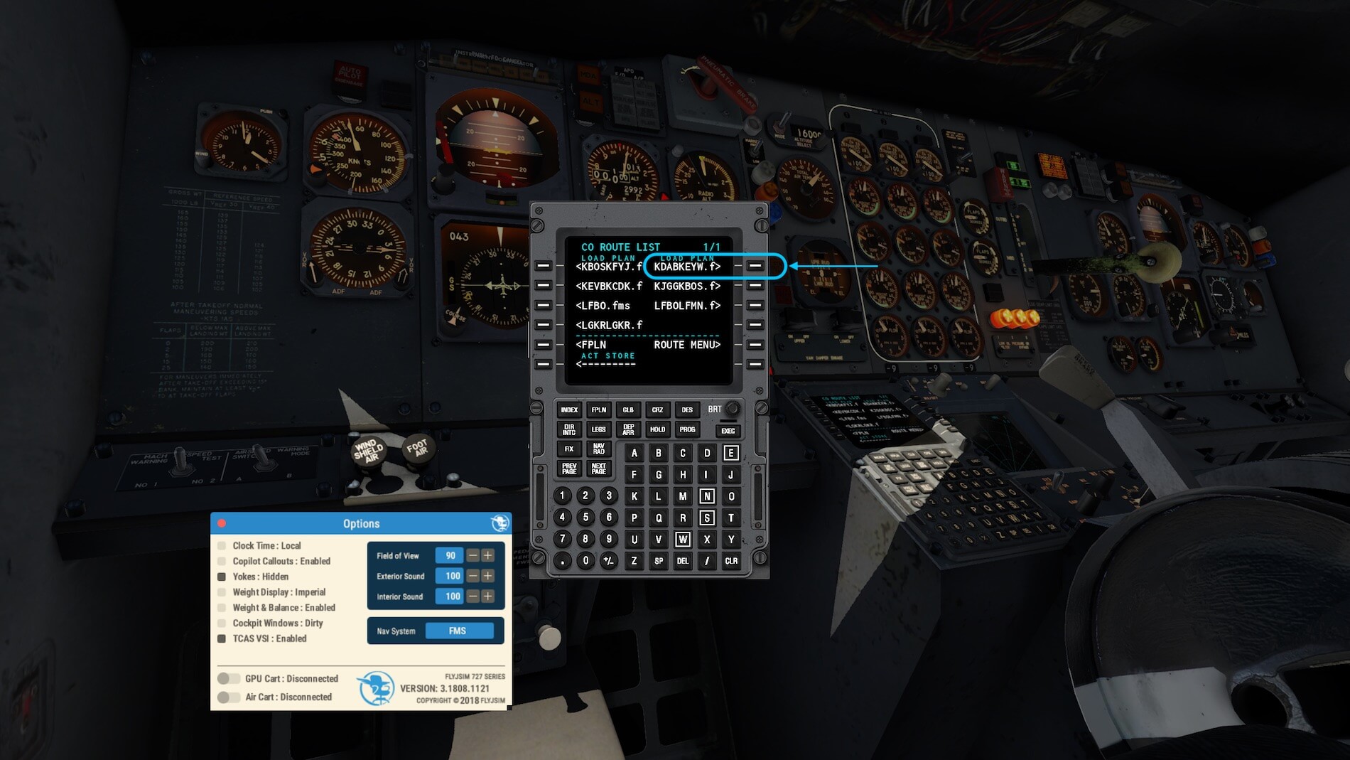
First, we need to implement with the FlyJSim Option tool the FMS. That’s not difficult since the FMS MCDU is a part of X-Plane 11. Before you know, we’ve got a MCDU on the left front of the pedestal. Assuming that I’ve copied and paste the KDABKEYW.fms flight plan in the Output/FMS plans folder, I can load it into the MCDU. As stated in the FlyJSim 727 Series manual on page 33 “We strongly recommend that you first read the Laminar Research documentation on using the FMS system. You can access the manual here” (http://x-plane.com/manuals/FMS_Manual.pdf).
Another thing to keep in mind is how to set the AP NAV selector. As stated in the previous section and referring to page 33 of the FJS 727 Series manual, I need to set the selector now to AUX NAV rather then NAV LOC. Remember, NAV LOC was used when we use VOR beacons for navigating or when you use it for the ILS localizer signal. And AUTO G/S was used for the ILS localizer and glide slope. Ok, one other selector knob position; TURN KNOB. Oops, that’s an easy one. With the selector know in the TURN KNOB, we can enter with the TURN knob a LH or RH ROLL thus an input from the aileron.

Still so far, it’s new, but for the rest, all the same. You do the same checks, you do the same taxi and the same takeoff. Ok, perhaps slightly different but you got the idea. What you do on the FD panel is not much different except, as I mentioned before, that for the NAV position you don’t use NAV LOC, but AUX NAV. AUX NAV is used not only for the FMS but also, when applicable, the xCIVA INS CDU.
After I’ve done my preparations, started the engines –worth to start the engines yourself and please don’t use for the sophisticated and well modeled engines the “started with engines running” option.
It’s time to taxi to the runway and double check everything and then, off I go. Hold on, did I forgot something …. ? Only thing besides the steps in the checklist is that I prefer to set the HDG bug at my runway heading. When I’m airborne, I prefer to set the AP in HDG and V/S mode, one of the basic AP modes of every aircraft.
You and I will notice that when you’ve connected the AP during your climb and disabled the HDG mode and replaced it with the AUX NAV, that the F/D and AP annunciator also shows a green GPS light. In this case the GPS is because the selector switch is set to AUX NAV and thus the AP follows the flight plan.
What said before, this way of lateral navigation with the help of the FMS is easy and straightforward. You can make it yourself as complicated as you want, you can read the Laminar Research FMS manual and see what you don’t want to explore or what you do want. For this review, detailed instructions on how to use the default FMS goes beyond the FJS 727 Professional v3 review.

Is the KEYW approach really different then with our VOR to VOR flight?
That depends if you have added a STAR at the end of your flight plan in the FMS MCDU. If not, then I suggest that you enter the ILS frequency of the runway you want to land and if you find that handy, an additional VOR beacon or, if not available, an NDB (for your ADF equipment) station.
At the end – a bit expected – it turned out that the workload with the FMS MCDU installed, has been reduced. Ok, we still need to think about V speeds, thrust or EPR selection, the right moment retracting and extended the flaps and landing gear and so on. And yes, the installed and well modeled Auto Pilot is old-fashioned, but as real as it gets. Yes, it’s weird to have a separate panel for the Flight Director and one panel for the actual Auto Pilot controls although all basic. No, it’s not weird! This is how it was in those days!


That Boeing and Airbus Auto Pilot or Auto Flight glareshield panels are so advanced, is no more then logic. Auto Pilot systems have evaluated from a simple box, to an advanced analog computer, to a basic digital computer to highly advanced Auto Pilot and/or integrated Auto Flight systems. But besides the integrated FMS with its MCDU and IRS (Inertial Reference System) and GPS (Global Positioning System), we had before the INS (Inertial Navigation System).
Worth to check this out, right? Also because the available xCIVA INS add-on has been recently updated for X-Plane 11.
Surprise …. Meet the Old Fashioned CIVA INS
The INS
The simulated INS (Inertial Navigation System) is a perfect companion for old-fashioned aircraft since, without this piece of hardware, navigation must be done with the help of VOR (VHF Omnidirectional Range) or NDB (Non-Directional Beacon) stations. In case you’re not familiar with VOR and/or NDB stations/beacons, I’ve added also the Wikipedia pages. Of course, many other websites are available that offer you thorough background information about these navigation aids.
Delco Carousel was a popular INS-based navigation automation system for aircraft developed by Delco Electronics. Before the advent of sophisticated flight management systems, the Carousel allowed pilots to automate navigation of an aircraft along a series of waypoints that they entered via a control console in the cockpit. The Carousel used an INS as its position reference for navigation. Many aircraft were equipped with dual or triple Carousels for redundancy. The Delco Carousel derives its name from the fact that the inertial reference platform is in constant rotation as a technique to reduce drift and increase accuracy.
Basic Construction
Consider an accelerometer as an instrument that measures acceleration along a single axis.
Integrate the output once, and you have velocity. Integrate again, and you have position – or rather, change of position – along the accelerometer’s axis. If you know the direction of travel, you can deduce current position.
Inertial Navigation is simply a form of dead reckoning. You need to know the starting point. An Inertial Navigation device/system can’t find its initial position on the earth (it can find latitude, with difficulty, but not longitude).
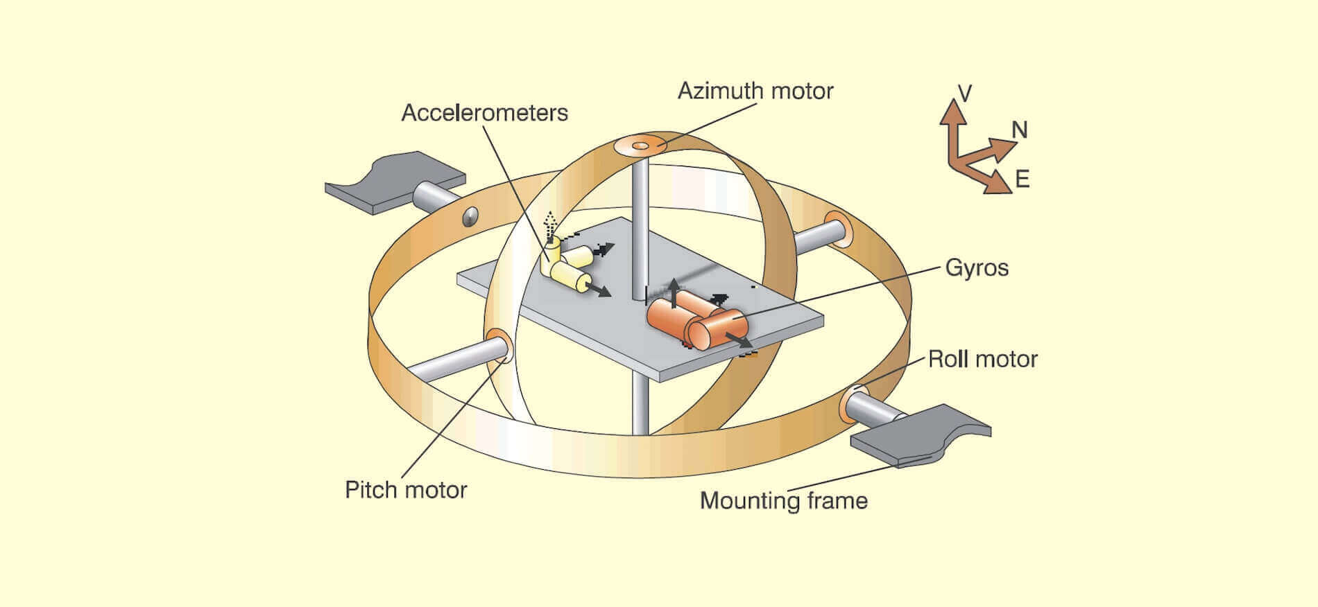
Take three accelerometers, with their sensing axes orthogonal. Arrange them so that their axes are aligned north south, east west, and vertical. To maintain this orientation when the vehicle maneuvers, the accelerometers are suspended in a set of three gimbals that are gyrostabilized to maintain the direction. Later we will be describing strapdown arrangements, but it always seems easier to explain the principles by starting with the gimbal model.
The gyros, similarly, are single axis devices, of a type known as integrating gyros – that is, they give an output proportional to the angle through which they have been rotated (about their input axes). The gyros are used as the sensing elements in null seeking servos, with the output of each gyro connected to a servomotor driving the appropriate gimbals, thus keeping the gimbal in a constant orientation in inertial space.
Integrating gyros also have what is called a `torquer’, a means of processing the input axis at a rate proportional to input current.

This combination forms a convenient means of cancelling out any drift errors in the gyro. The gimbals, as shown in the figure, (well, they may be there but they are not identified) have a bearing at each end. Each has a motor, built around one of the bearings, and at the other end a synchro.
No matter how the aircraft maneuvers, the innermost gimbal maintains its orientation in inertial space. The synchro on the innermost gimbal thus measures azimuth (or heading), the synchro on the middle gimbal measures pitch, and the outer gimbal measures roll.
The innermost gimbal can be thought of as a stable platform on which are mounted the gyros and accelerometers although, in practice, it looks like anything but a platform, being a miracle of mechanical packaging.
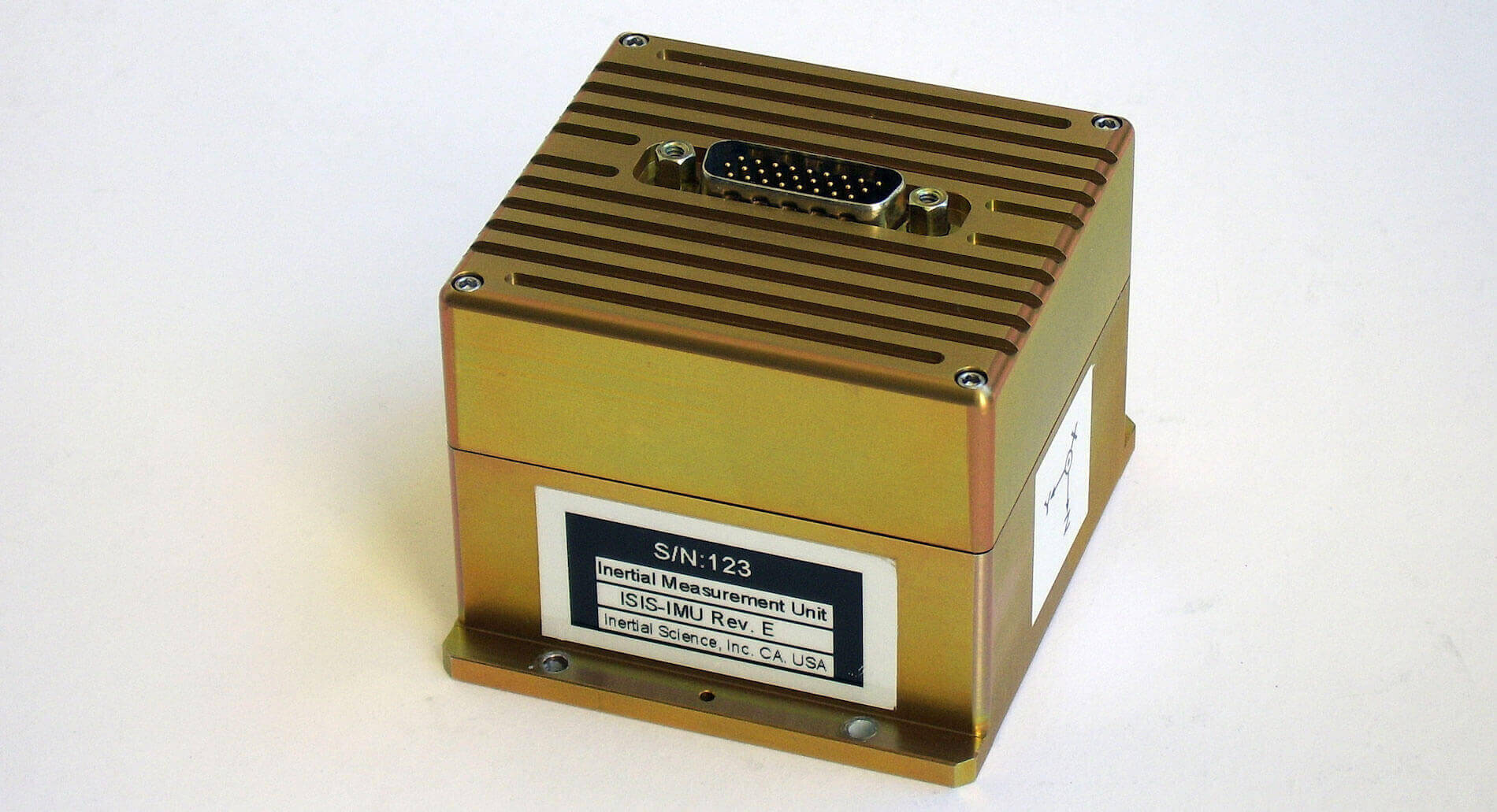
The whole arrangement is generally called a gimballed platform. Find on your left an example of an Inertial Measuring Unit (IMU), which houses not only the gyros, motors, gimbals but also the accelerometers.
Simplified Operation
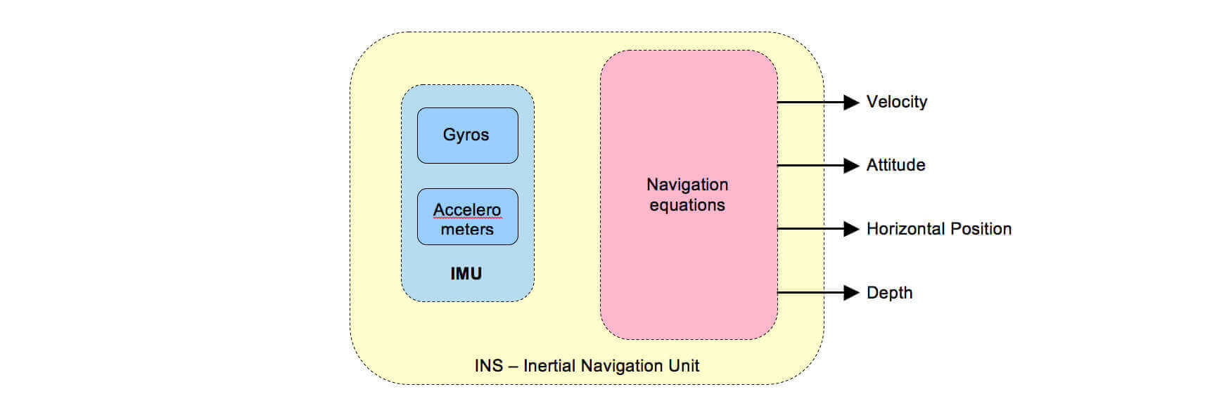
As said before; the IMU is an electro-mechanical device consisting of accelerometers and gyroscopes. The accelerometers are mounted on a gimballed platform in a way that the axes of the devices sensitive to acceleration were mutually perpendicular.
At the beginning of the flight, an IMU is aligned although some say too quickly that the INS is aligned. Just to make sure; INS is a system, comprising all the components together like the IMU(s), Mode Selector Panel(s), CDUs (Control Display Unit) etc. The pilots provide the CDU with the current position of the aircraft. The system stores this information and aligns the gimballed platform to a set attitude with reference to the Earth.
The gyroscopes were set up to measure the rotational displacement and velocity of the aircraft about the longitudinal, vertical and lateral axis of the aircraft. Basically, what happens is that the gyroscope signals are used to mechanically rotate the gimbaled platform in a direction opposite to what the aircraft is doing.
This maintains the accelerometers in the same attitude relative to the Earth that they were established in during the alignment process. Thus, if one accelerometer was aligned East-West, and one North-South, this alignment would be maintained no matter the attitude of the aircraft.
The accelerometers would generate signals proportional to the accelerations in the E-W and N-S directions. This acceleration data can be directly integrated once to get velocities in the E-W and N-S directions, and integrated once more to get displacements or navigation data in the E-W and N-S directions.
The xCIVA INS Add-On
Although I’ve mentioned it before, highlighting it once more can’t be a problem. The X-Plane developed CIVA INS can be found at the dedicated X-Plane.Org web page. According to X-Plane.Org, “The original CIVA INS could be found on the Boeings 707, 727, some 737-100s and -200s, the DC-10, the L-1011 Tristar, and on the early 747-100, -200 and -300 variants.”
The CIVA INS package comes with the following features:
– Fully compatible with the FJS 727 Series by FlyJSim
– Realistic warm-up, initialization and alignment procedures
– Optional Quick-Align to get you flying instantly
– All display modes modeled, including HOLD modes:
– Automatic navigation of up to 9 waypoints
– XP flight plans can be loaded instead of manual WP entry
– Single-DME updating incorporating DME elevation
– Realistic position drift and smooth updating
– Built-in 30-minute backup battery in case of emergency
Package and User Guide
Ok, suppose that after reading this review you’ve also become enthusiastic about the CIVA INS add-on, and decided to buy your personal CIVA INS copy, it’s time to see what you get. So, you’ve downloaded (xciva-131-XP1120.zip for X-Plane 10.20+) and unzipped it. You end up with a folder “xciva” that contains:
– the actual plugin xciva (Linux, macOS, Windows and a Resources folder)
– CIVA-User-Guide.pfd
The CIVA User Guide comes among a few other chapters with:
– Inertial Navigation – An Introduction
– Installation
– The CIVA Popup window (via XP menu)
– Keyboard entry, basic modes and navigating
– The Hard mode (Cold & Dark situation)
– Display modes
– Leg change and DME updating
The manual seems to offer all the information what is needed to understand CIVA INS, it’s in my opinion not in a user-friendly way written. This is for example with chapter 8, which is far too much text and hardly any pictures to highlight certain process changes or visualize the steps to be taken.
Installation
Next step; where to install the xciva folder?
Install the “xciva” folder in the X-Plane “Aircraft/ 727_Series_Pro_V3_-100 (or 727_Series_Pro_V3_-200Adv or 727_Series_Pro_V3_-200F)/plugins” folder.
When you prefer to use the popup xCIVA INS, then go to the X-Plane Plugins menu and select CIVA. A sub popup window appears with only two options; Show/Hide. When there’s no CDU in view, you (logically) click Show. And here you are, the floating CIVA INS add-on.
But it should be noted that once you’ve installed the xCIVA plugin, the FWD pedestal mounted INS CDU becomes fully operational and fully functional as with every other modeled equipment. This gives it a realistic look and feel and the popup INS CDU is then more for your convenience since there’s no need to look down on the pedestal to see the CDU while flying.

INS Videos
Searching YouTube for the CIVA INS operation, I found four movies that could be of interest. These videos show you a different INS CDU, not the one developed for X-Plane, but it should give you a better understanding how to handle this INS CDU and the Mode Selector Unit.
– CIVA INS tutorial I
– CIVA INS tutorial II
– CIVA INS tutorial III
– CIVA INS tutorial IV
Using xCIVA INS
When using the xCIVA INS add-on on your flights, you’ll notice that the way you use this navigation device isn’t different then using the default FMS MCDU. Connecting the INS to the aircraft AP is the same as when you use the FMS.
That said, with a connected AP, the AP will follow the flight plan loaded in the INS by clicking the NAV/LOC button on the left-hand side of the glareshield. The popup xCIVA INS consist out of two components; the INS MODE SELECTOR panel and the INS CDU. Both are functional and work according to what is written in the CIVA manual. And, as said before, the pedestal mounted INS CDU is also functional.
Ho ho, hold on.
There’s something important to tell you. According to the developer “The easiest way to use CIVA for X-Plane is loading up the aircraft with engines running, and then loading an X-Plane flight plan. Please note that even in Easy mode, the waypoint storage is restricted to 9 waypoints, just as in the real unit. Therefore, you can only load up to 9 waypoints from an X-Plane flight plan!”
“After loading a fight plan, the waypoints 1-9 are programmed according to the fight plan. You may now use the Autopilot in AUX NAV mode to fly the route. If you load a flight plan in flight while enroute to your 9th waypoint, only waypoints 1-7 will be loaded from file to not disturb your current leg to point 9.”
That’s it! Up we go for our fourth test flight with the xCIVA INS installed.
Fourth Flight Impression (Using xCIVA INS)
Preparations
If you use the “Easy” or “Hard” xCIVA INS mode, is up to you. When you don’t like to start the aircraft with “engines up and running”, but from a cold and dark situation, then I suggest that the xCIVA “hard mode” description item 8 of the xCIVA manual is the best way. After you followed and performed the INS warmup and alignment steps, you can always load a prepared flight plan, stored in the X-Plane folder FMS plans.
If you don’t like that, you can decide to enter the waypoints manually. Keep in mind that waypoints that are entered in the xCIVAS INS must be in the format degrees, minutes, tenth of seconds. As stated in the xCIVA manual “You get the coordinates from your airport chart, alternatively you can look them up on sites like http://airnav.com. You can also use X-Plane’s Data In/Out feature to display the current latitude and longitude of your aircraft, and then use a calculator like http://www.directionsmag.com/site/latlong-converter/ to convert from decimal degrees to degrees, minutes, tenths of minutes.”
Another option according to Philipp Ringler, the xCIVA INS developer is using SkyVector to make your flight plan. Although SkyVector uses as different extension (fpl), the printed navigation log shows you the latitude/longitude coordinates in the correct figures.

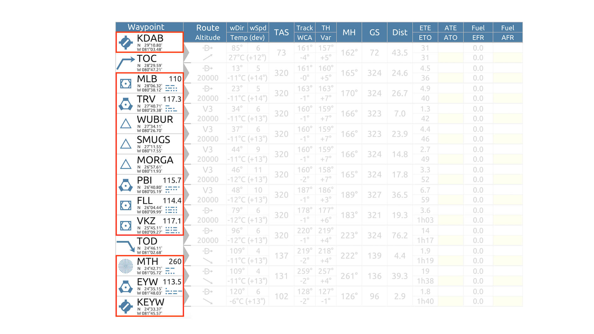
This INS flight impression is based on my previous KDAB to KEYW flight. I have already a flight plan – although I won’t use it – and a printed navigation log retrieved from SkyVector. Since I prefer manually adding waypoints into the INS CDU – this is as real as it gets, and this is the way pilots did it this way too – I enter some of the waypoints found on the previous navigation log.
After consulting a couple of persons regarding entering the correct latitude/longitude data, I would highlight the following. The lat/long positions given by X-Plane can’t be used for xCIVA as well as lat/log data that represents degrees . minutes . seconds. The only data that is valid for xCIVA is degrees . minutes . tenths of minutes. Don’t worry to much, here’s some help. What I wrote before, the navigation log from a create SkyVector flight plan shows right away the correct degrees . minutes . tenths of minutes. In case you have the wrong values, lets say you have X-Plane coordinates, you can use this link (http://www.csgnetwork.com/gpscoordconv.html) to figure out the equivalent degrees . minutes . tenths of minutes as well as degrees . minutes . seconds.
After I’ve done the necessary checks and entered the following waypoints (see below in the correct format), I’m basically ready for my flight.
Initial position “Daytona Jet Aviation” : N 29.11.13 / W 81.03.21
Waypoint 1: MLB | N 28.06.32 / W 080.38.12
Waypoint 2: TRV | N 27.40.71 / W 080.29.38
Waypoint 3: SMUGS | N 27.11.55 / W 080.17.55
Waypoint 4: PBI | N 26.40.80 / W 080.05.19
Waypoint 5: FLL | N 26.04.44 / W 080.09.99
Waypoint 6: VKZ | N 25.45.11 / W 080.09.27
Waypoint 7: MTH | N 24.42.71 / W 081.05.72
Waypoint 8: EYW | N 24.35.15 / W 081.48.03
Waypoint 9: KEYW | N 24.33.37 / W 081.45.57


The Flight
Since I did already several flights, it doesn’t add anything by writing again … the taxi is nice, I have a good takeoff, climb goes well and so on. I did that already. I’m more interested how to handle the 727 with as navigation aids the xCIVA INS and if my workload is higher then without the INS or the same as during my FMS flight, right?
I can tell you; it’s roughly the same workload as when you have the FMS MCDU. The steps to follow and to connect the INS to the Auto Pilot are the same as with my FMS. That said, you set the NAV SELECTOR on the AP panel to AUX NAV. And, there’s a slight change with version update 3.1808.1121a, you set the NAV-GPS switch on the captain’s instrument panel to GPS. This is basically what’s different, if I can speak from a difference. The pitch channel controls, activations are the same as during my previous AP flights.
And what else can you do when the INS is providing the LNAV?
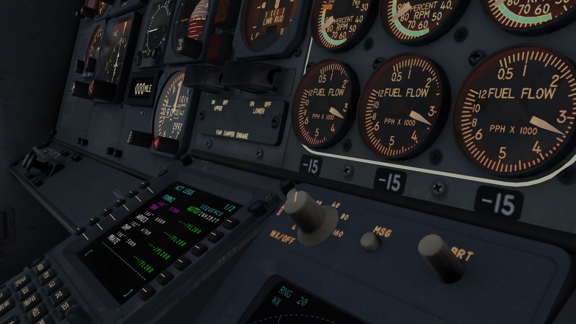
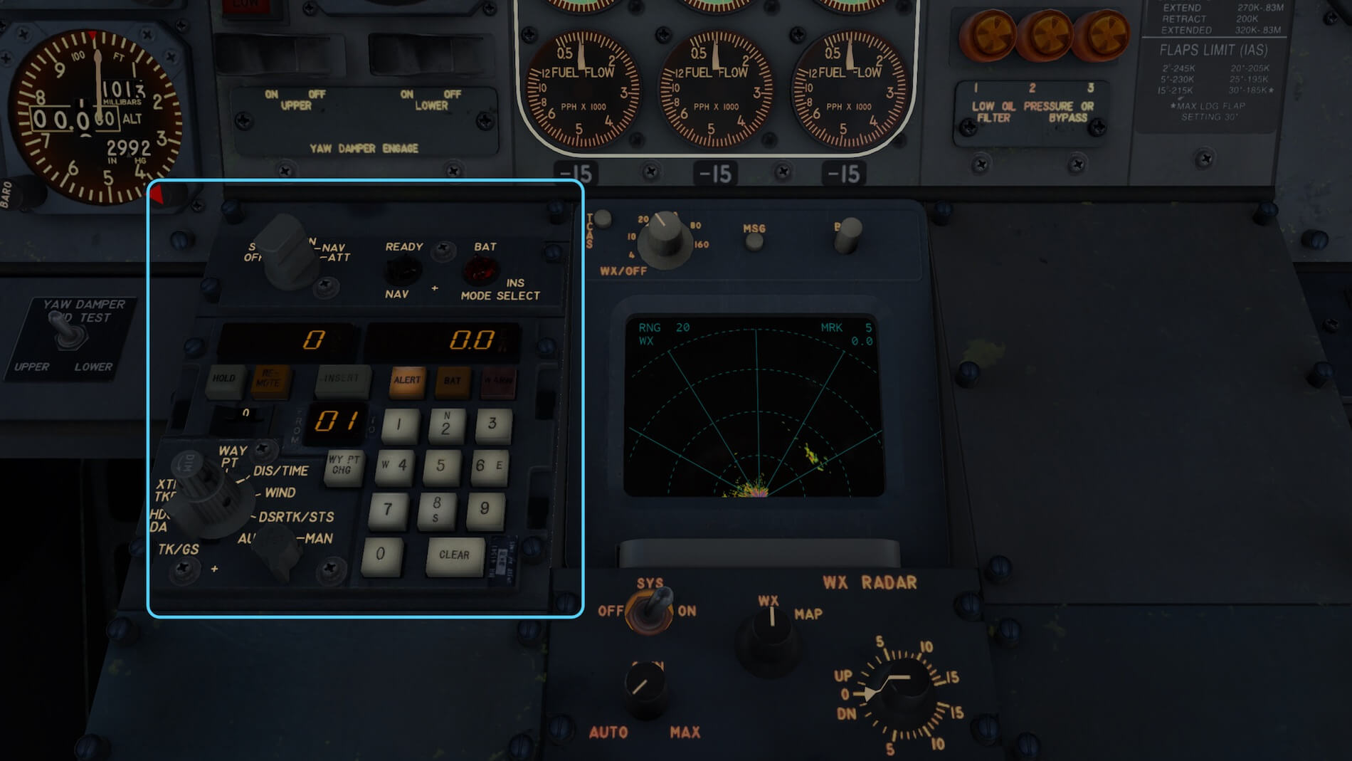
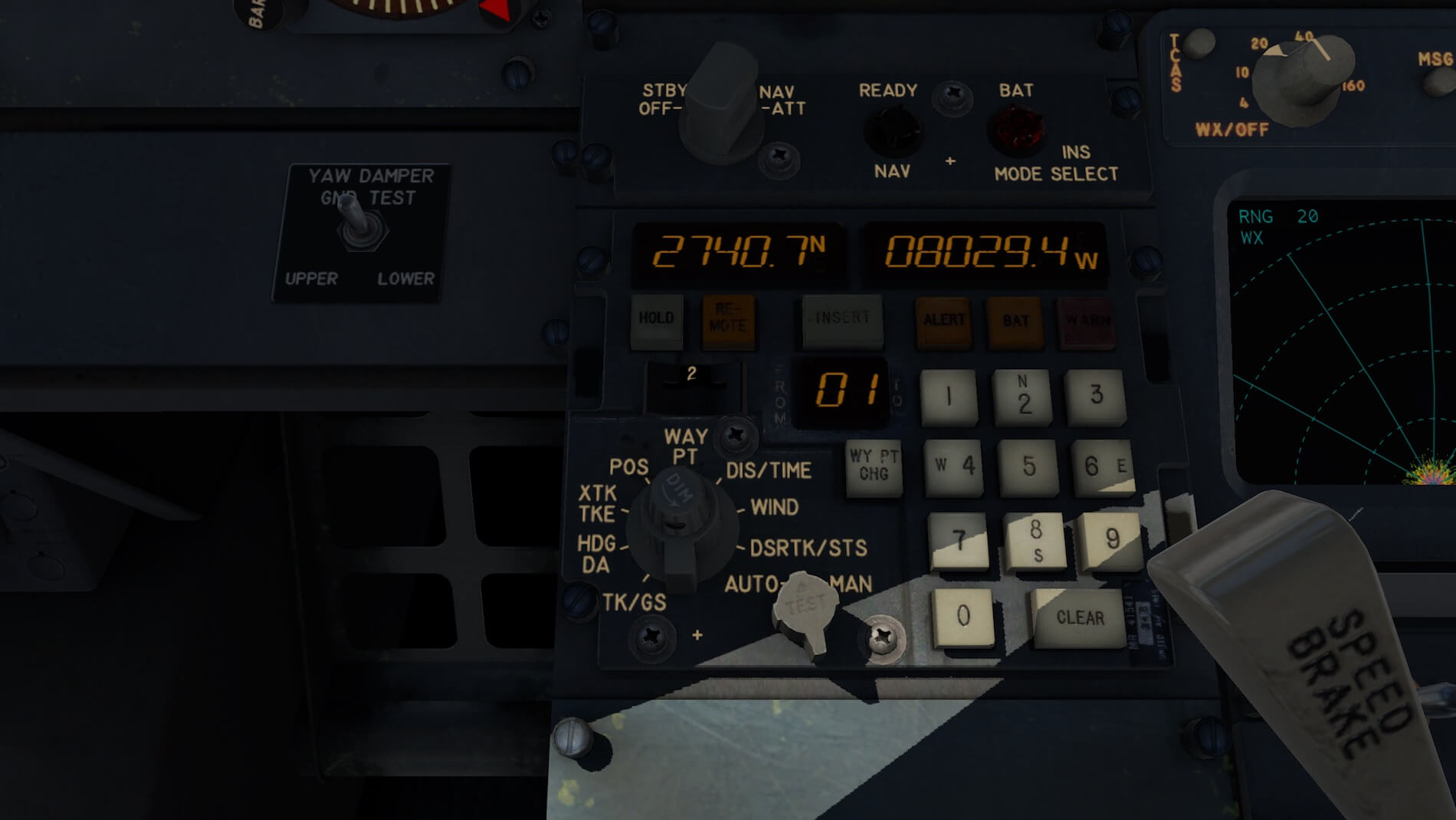
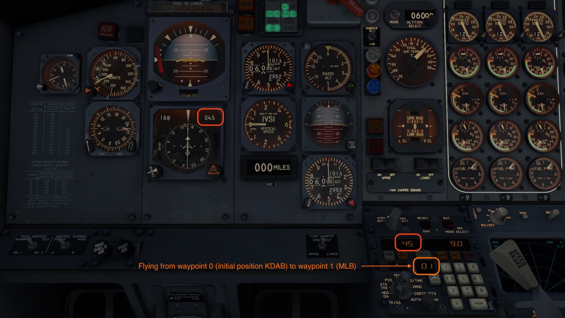
You can play a bit around when the 727 is leveled off by changing the data selector on the INS CDU. Try for example the position DIS/TIME. This gives the distance to go and time in minutes to the next waypoint. When the FROM-TO indicator on the INS CDU shows 01, it means you’re flying from your initial position (KDAB Daytona Jet Aviation) to the first waypoint which is in this example MLB (Melbourne) and so on.
When you select XTK/TKE (Cross track and track angle error), you can see and monitor if you’re off track towards MLB. In other words, with this data selector you get a lot of info how the nav is doing. Worth to check the provided INS manual section “9 Display Modes”.


The remainder of the flight including a RNAV landing at KEYW isn’t different then my previous approaches/landings, but perhaps there’s one thing I need to bring up and hopefully, it will or can be solved although no idea who can or will do this.
I’m talking about loading a flight plan with the xCIVA INS CDU v1.3.1 installed on a macOS platform. For some reason I wasn’t able to see my stored flight plans (FMS plans). It was there, but when trying to find it using the REMOTE button on the CDU, it doesn’t show it while I was testing this with Windows simmers and Org user Cessna729 and even Philipp Ringler. They all have Windows and they could see the fms file(s).
That said, it turns out that on a Mac with xCIVA 1.3.1 stored fms files aren’t visible and because of that, as of this writing end of August 2018 – you need to enter the waypoints manually. I also tried to install the older xCIVA v1.2 with XP11.25rc2, and then in a sudden the flight plans are visible when using the REMOTE button, but I had the idea that it didn’t do its job well during flight.
End of the story; as it looks now, on a Mac you need to use xCIVA version 1.3.1 in combination with X-Plane 11.25 but you won’t see stored fms flight plans. That said, you need to enter the flight plan waypoints manually! When you have a Windows computer, you won’t have these problems. Any comment or own experience, please let us know!
Anything Forgotten?
I think I haven’t forgotten anything, but the moment the review is online and comments of simmers pop-up, I suddenly face things I haven’t highlighted. Let’s remind ourselves that this review is a “review of a product” and not a tutorial of how to fly the FlyJSim 727 v3 Professional.
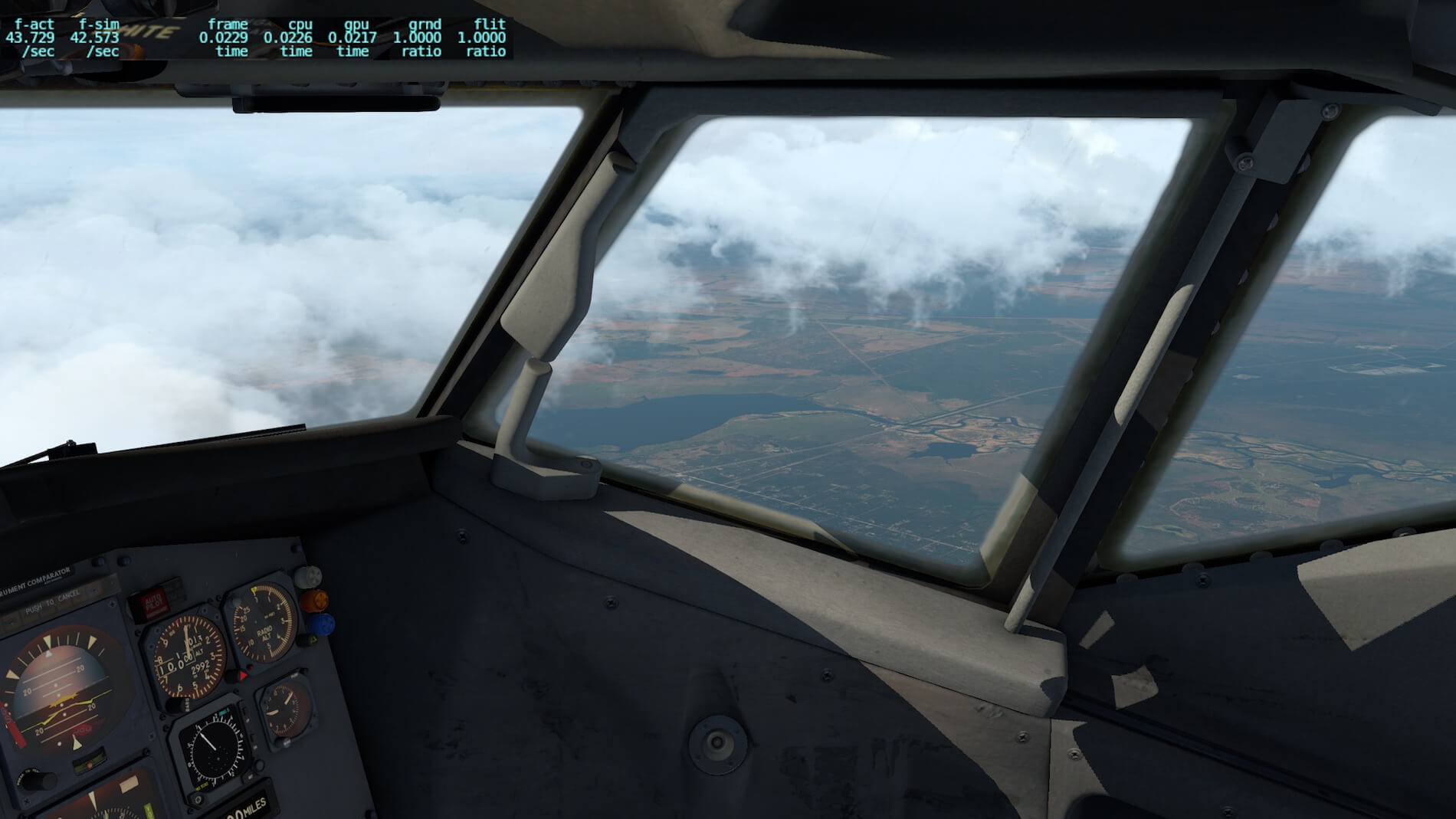
When it comes to frame rate values, it’s always a matter of your PC or Mac specifications and how high you’ve set your X-Plane 10 Rendering Options. In my case, they are set quite high for a realistic external look and giving me the possibility to make impressive screen shots. And then, still with these high Rendering Options, I’m able to get at least 30-35 FPS (Frames Per Second). I’m aware that frame rates will drop a bit or dramatically when you’ve landed on a medium to complex airport. Are higher frame rates possible? Oh yes, by reducing the rendering settings to more normal values and you easily get 35+ frames. Check out this …….


Looking at the Sound folder of each 727 package I count roughly 8Mb of sound files which gives me a good feeling. Although I’m not familiar with the Boeing 727, I’m familiar with the JT8D sound and that tells me that I deal with a realistic engine sound. Checking the dedicated 727 FlyJSim website for background information about these sound files, I found the following information;
They called it the whisperjet… but the sounds are anything but quiet. Continuing from the success of the 732 Twinjet, FlyJSim has developed an accurate and immersive FMOD sound pack, which provides a fully 3D positional experience. Experience the realistic screech of a 727 JT8D engine at full power. You will hear every engine, switch, and greased trim wheel. Definitely an experience you will want to keep the headphones on for!
Summary
Before I begin, first some details like … what X-Plane version(s) I used, which OS I have and perhaps the add-on packages I have installed.
– iMac Pro Model build 2017 (see hardware specs below)
– macOS High Sierra 10.13.6
– X-Plane 11.25r2
– Freeware: FlyWithLua for X-Plane 11 v2.6.7
– Freeware: Environment+ v1.1
– Freeware: AlpilotX.Net HD Mesh v4
– Freeware: AlpilotX.Net UHD Mesh v4
– Freeware: MisterX6 Boston Logan Airport v1.0
– Freeware: MisterX Library v1.61
Should you own the FlyJSim 727 Professional v3? I think it should be in your hangar, even when you’re a modern electronic computerized flight simmer. When you like old-fashioned aircraft and like to fly only with the help of VOR/VORTAC and NDB beacons, then this is your companion. But it’s even possible to add to this aircraft the “as real as it gets” Delco CIVA INS unit.
Either combination is possible and for the price of the CIVA, only 12.00 USD, you can add it always to the aircraft and then it’s up to you if you decide to use it or not. If you prefer a FMS MCDU then you have the option to implement the default Laminar Research MCDU too.
It’s a well modeled with an awesome 3D cockpit. I found no gaps between the individual panels, great looking instruments from a distance and when zoomed in. The switches, knobs, lights, handles etc. are well modeled, have a weathered look, when applicable and complete the overall old-fashioned cockpit. Even the FE panel is modeled in great detail, but above all, many aircraft systems are developed with the greatest accuracy.
It’s also worth to highlight the accuracy of the external 727 models. Although not always directly in the spotlight, the landing gears are made with great precision, as is the operation of the leading and trailing edge hi-light devices and the engines too. Regarding the engines, it’s worth telling you about the great details in the modeling of the internal thrust reverser buckets.
Although you hardly see “clean” reverser like the ones that are modeled, they are modeled and work OK. External lighting comes to life when you have set the visual effect to either High or plus. The result is a stunning external lighting system and please, don’t forget to have a look to the old-fashioned rotating anti-collision lights. Overall, the FlyJSim offers a great external 727, but also a great aircraft to fly with.
What else?
The FlyJSim 727 manuals are OK although I personally miss a soft/hard copy of a tutorial. You can grab the FlyJSim 727 via X-Plane.Org via the following link. In case you’re also interested in the add-on CIVA Navigation System for 12.00 USD.
And if this isn’t enough, I’m pleased to offer a couple of interesting links:
– Aviation For All “722 Airplane Operations Manual
– Informative and dedicated Boeing 727 Series website
– Boeing 727 Airplane Characteristics Airport Planning
When you know another interesting Boeing 727 website, please let us know! You can contact us via info@x-plained.com.
Did I cover every bit and piece of this marvelous Boeing 7237 replica?
I tried to cover as much as possible. I tried to offer several “possible” flights. Each flight represents a navigation aid and although the FMS and INS equipped flights are more to show you how to handle ratter then including a complete landing, they should give you a good idea. While writing this, I’m also aware that I hardly covered the F/E (Flight Engineers) panel.
This is partly because I’m a lonely virtual pilot sitting in this complex flight deck. Yes, it is complex. An old-fashioned highly realistic aircraft model like this FlyJSim 727 Professional, but also applicable for their 732 Classic v3, don’t offer many systems that reduce the pilots workload like ECAM or EICAS. In that respect, these FlyJSim aircraft bring you back to school where dead reckoning, and ordinary navigation was instructed. Awesome (when you like it)!
Finally, some words about “how does it fly and if it flies, does it fly like a real 727?” Although I’m the frozen owner of a FAA PPL on a Cessna 152 and 172, it’s still very difficult to me to judge if it flies realistically. Only real licensed ATPL pilots can judge if a modeled X-Plane aircraft flies close to the real aircraft. The best would be when it is somebody who flies or flew the real 727, but even any other aircraft would help.
I’ve got the feeling that this old-fashioned Boeing 727 Series flies as real as it is possible and worth being a member of your fleet!
Feel free to contact me if you’ve got additional questions related to this impression. You can reach me via email Angelique.van.Campen@gmail.com or to Angelique@X-Plained.com.
With Greetings,
Angelique van Campen
| Add-on: | Payware FlyJSim 727 Professional v3 |
|---|---|
| Publisher | Developer: | X-Plane.Org | FJS |
| Description: | Realistic rendition of Boeing 727 Series |
| Software Source / Size: | Download / Approximately 2.4GB (unzipped) |
| Reviewed by: | Angelique van Campen |
| Published: | August 25th 2018 |
| Hardware specifications: | - iMac Pro - Intel 3GHz Intel Xeon W / 4.5Ghz - Radeon Pro Vega 64 16368 MB - 64 GB 2666 MHz DDR4 - 1 internal shared 1TB SSD (Big Sur 11.x) - 1 internal shared 1TB SSD (Bootcamp Windows 10) - 1 external 2TB LaCie Rugged Pro SSD (Big Sur 11.x) - Saitek Pro Flight System X-52 Pro and X-56 Rhino - Honeycomb Alpha Flight Controls - Honeycomb Bravo Throttle Quadrant |
| Software specifications: | - macOS Big Sur (10.15.x) - X-Plane 11.5x |
5 Comments
Submit a Comment
You must be logged in to post a comment.
I’m sorry guys but I do not agree. They amount of FPS’s are important as well. More eye candy = less FPS.
Besides that most add-on makers for X-plane are small teams with low financial resources. In my opinion this add-on is one of the best add-ons for X-plane.
I like the 727 a lot. I love flying it.
But the lack of a cabin makes me disappointed. It reminds me of XPlane 8 where there were NO cabins at all. The builder says the Cabin of the 727 is not important and you do not need it to fly. Well, if that is the case, why bother with a exterior model? You do not need it to fly the plane. A pilot is in the cockpit and he does not need to see the cabin or the outside of the plane for it to be an in depth swimming experience.
For my heart I love the Sim 737 with the cabin and all. but I am indifferent to the 727.
Just my opinion.
Hi Donald, it’s also a matter of taste! I know what you feel and what you prefer and yes, I would like to have it too, but for me it’s even more important that thew 3D cockpit is perfect, that thew systems are well simulated and that the model offers as far as possible, real flight dynamics. Personally, that’s for me even more important then having a Virtual Cabin. But again, it’s what everybody likes or dislikes.
I agree with Donald, it is the same reason why I won’t buy the IXEG 737, for all the money, why leave out the cabin, Donald, you made a very good point, and I won’t buy the 727 either, if I am going to spend my money, I would like to feel I spend it well and feel happy of my purchased. It’s one of the reasons why I review before I buy, because I know everyone has their own opinion and will point out these factors.
I forgot to add, when a developer is creating a product that will be sold to others, you are not creating it for yourself so saying that cabin is not needed, that is your opinion, in other words, you are not interested in selling your product, you might as well not sell it at all.