Peters Aircraft “Fokker-VFW 614”
The VFW 614
Although this weird looking aircraft was well known as the VFW 614, it was officially a merge between Fokker Netherlands and VFW (Vereinigte Flugtechnische Werke). What said before, the VFW614 is a weird looking aircraft or was it only because of the location of the engines? The VFW 614 was, for those days, an extraordinary aircraft design. Perhaps the bad part is that it was never a success, neither less, worth to have a look into Peter Hager and his team latest X-Plane 10 and X-Plane 11 Public Beta creation. The review is based on product version 1.4.

The following paragraph was added at the last moment – the review was officially finished – after I found out that I did something wrong which gave you and me a different VFW INS behavior than expected. Mystery, isn’t it? Let me explain.
The review offers three different test flights, all from EDDM to EDDL. The difference lies in how to navigate.
The first flight uses ordinary navigation aids like VOR, eventually a NDB beacon (ADF) and flying HDG mode thus this first flight doesn’t use the build in VFW INS and in mainly intended to explore the modeled aircraft.
The second flight uses, weird order, I know, the build in VFW INS, but with installed although not using, the CIVA INS plugin.
And finally, the third flight does the same as the second flight, but now I removed the CIVA plugin from my X-Plane configuration thus the VFW INS behaves as it is by default.
To summaries the above:
– First Flight without using VFW INS, using VOR, ADF and HDG mode.
– Second Flight using the VFW INS. CIVA add-on plugin installed, but not using it.
– Third Flight using the VFW INS and no CIVA plugin installed.
I can tell you already that buying the CIVA INS from X-Plane.Org is worth it. No no, I don’t get any money from X-Plane.Org to promote this, but it adds so much more functionality to the build in default VFW INS. As far as I’ve seen during my tests, the way the default VFW INS behaves without or with the CIVA plugin installed, is huge. I can imagine that you don’t like the popup version of the CIVA INS add-on. I don’t like it either, but instead, you can use the VFW INS which is suddenly transformed into a comprehensive INS unit.
Anyway, you can read all about it in this in-depth VFW 614 review.
Do you join me on my VFW 614 adventure?
But First … a Table of Contents
Due to the length of this impression, with all the sections including the CIVA INS add-on, I’ve decided to include a table of contents.
But First …. some VFW background
What do You Get?
First Flight | VOR, HDG etc.
– Introduction
– Quick Start Procedures
– Some notes/remarks
– Starting the Test Flight
– Cockpit Impression
– Passenger Cabin Look and Feel
– Continuation “Starting the Test Flight”
Second Flight | Using VFW INS Configuration I
– Working with VFW INS with CIVA plugin installed
– VFW INS Explanation
– Preparations and ….
– In Flight VFW INS Behavior
– Frame Rate Impact
Third Flight | Using VFW INS Configuration II
– Introduction
– Some VFW INS notes
– VFW INS Explanation WITHOUT CIVA plugin
– And … Now in Flight?
Meet the Old Fashioned CIVA INS
– Introduction
– The INS
– Basic Construction
– Simplified Operation
– The xCIVA INS Add-On
– Package and User Guide
– Installation
– INS Videos
After Landing Check
VFW 614 Walk-Arounds
And at the End
But First …. some VFW background
The VFW-Fokker 614 (also VFW 614) was a twin-engined jetliner designed and built in West Germany. It was produced in small numbers by VFW-Fokker in the early- to mid-1970s. It was originally intended as a DC-3 replacement. Its most distinctive feature was that its engines were mounted in pods on pylons above the wing.
The VFW 614 was originally proposed in 1961 by the Entwicklungsring Nord (ERNO) group, comprising Focke-Wulf, Hamburger Flugzeugbau (HFB) and Weser as the E.614, a 36-40 seat aircraft powered by two Lycoming PLF1B-2 turbofans. West German industry was subsequently reorganized and Vereinigte Flugtechnische Werke (VFW) was established at Bremen. Development of what was now the VFW 614 continued.
Although Lycoming abandoned the PLF1, development continued using the Rolls-Royce/SNECMA M45H turbofan, which was developed specially for the VFW 614. In 1968, the project was given the go-ahead, with 80 percent of the backing from the West German Government. Full-scale production was approved in 1970, by which time VFW had merged with Fokker (a somewhat unhappy arrangement which lasted for only ten years). Also, risk sharing agreements had been concluded with SIAT in Germany, Fairey and SABCA in Belgium and Shorts in the UK. Final assembly of the aircraft would be done in Bremen.


The first of three prototypes flew on July 14, 1971. The first flight of the aircraft was also the first time the engine had been airborne as it had not flown on a flying test-bed. The aircraft had an unconventional configuration, with two quiet, smokeless, M45H turbofans mounted on pylons above the wings.
This arrangement was used to avoid the structural weight penalties of rear mounted engines and the potential ingestion problems of engines mounted under the wings. This allowed a short and sturdy undercarriage, especially suited for operations from poorly prepared runways. The position of the engine over the wing, compared to under-wing, also shielded people on the ground from intake noise during flyover. This shielding is also present for aft-mounted engines. You can read all about it at the dedicated Wikipedia web page. (Courtesy of Wikipedia)
What do You Get?
Perhaps not always the most exiting paragraph, but it is needed to give you an idea which or what stuff you get when you buy the VFW 614 product package version 1.4 which was released within February 2017.
The download consists of 3 packages:
– Authentic manuals
– Quickstart manual
– the aircraft package itself
Don’t be shocked …. the authentic manual package is approximately 750Mb (unzipped). When unzipped, it offers approved and non-approved authentic handbooks, a pilot training manual from 1976, a refresher course manual and two different brochures that promote the wonderful VFW 614. Is it worth to print these manuals? I could say that it’s worth it, but added immediately to it ….. the approved handbook is 304 pages so a lot of ink or toner is needed. You can also read the manual via another PC or Mac or even on a tablet. Up to you!
Printing or not, this is different for the quick start manual. It’s a Peters Aircraft design, only 48 pages. It’s not a tutorial, but as the name suggests, a quick start guide. That said, it offers panel locations, how to handle the aircraft with engine running or how to handle the aircraft from a cold and dark situation. Also important is how to deal with the VFW integrated INS and as Peter says himself …. “We decided to implement this rudimentary FMS capacity as a last minute-quick-shot of the initial release. A lot more attractive is a third-party plugin named CIVA or xCIVA, which simulates a very similar INS type, and can be used together with this model.”
While it is worth to highlight that Peter also suggest to go for the “CIVA which simulates a very similar INS and can be used together with this model. The CIVA plugin can be purchased from the X-Plane.org store. Presently it’s price is at $10 only, and it’s really recommendable!”
Want to learn more about the CIVA INS?
Then you should check our review at X-Plained after you’ve finished reading this VFW 614 impression.
And finally, the aircraft package.
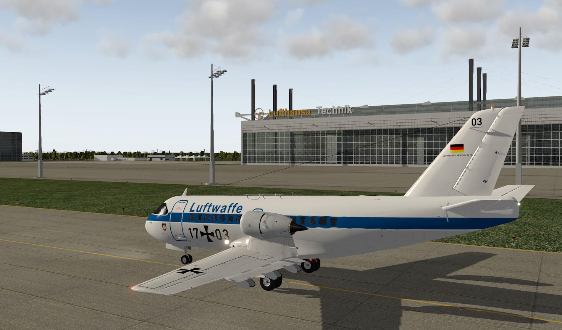
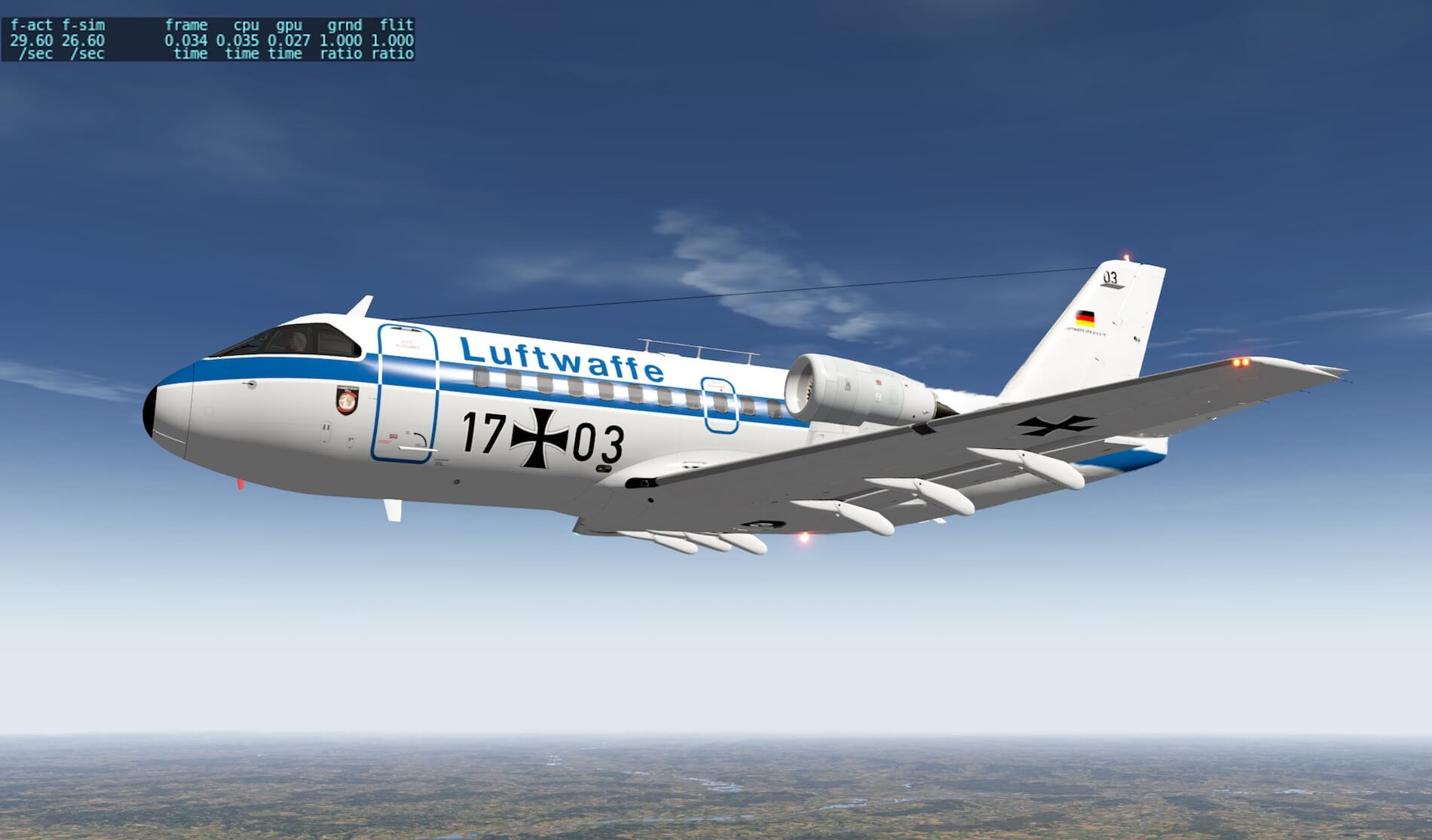
The package consists of the VFW 614 which has no “- number” as with other modern aircraft like -200, -400 or whatever is applicable. That said, the VFW 614 was only available in one model which could offer place to approximately 40 passengers. It comes with 5 liveries from:
– Luftwaffe
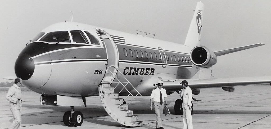
– Cimber (Sterling, which is/was a Danish airline)
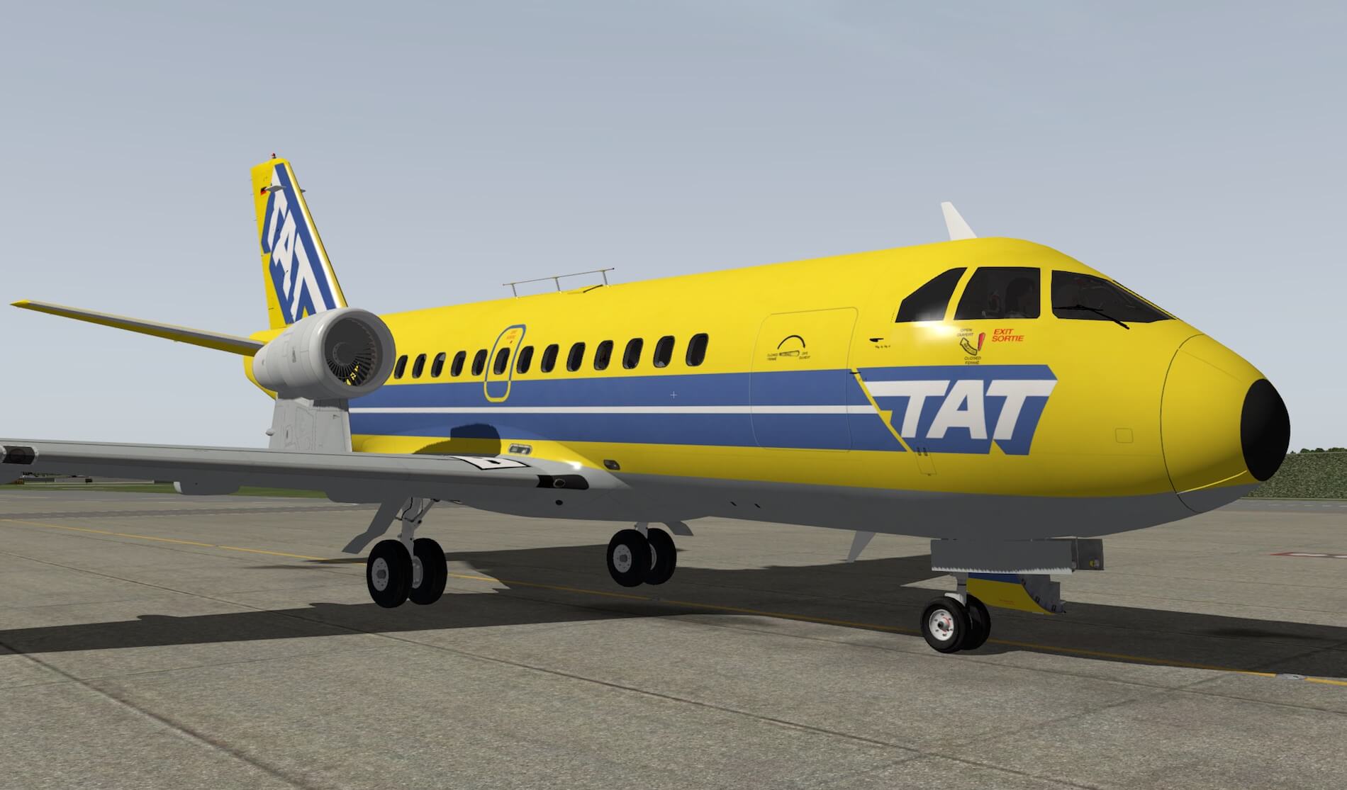
– TAT green (Touraine Air Transport)
– TAT yellow
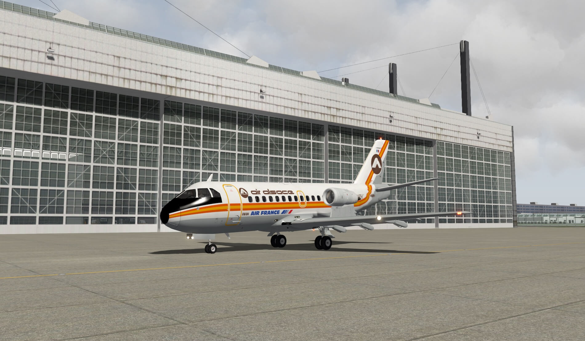
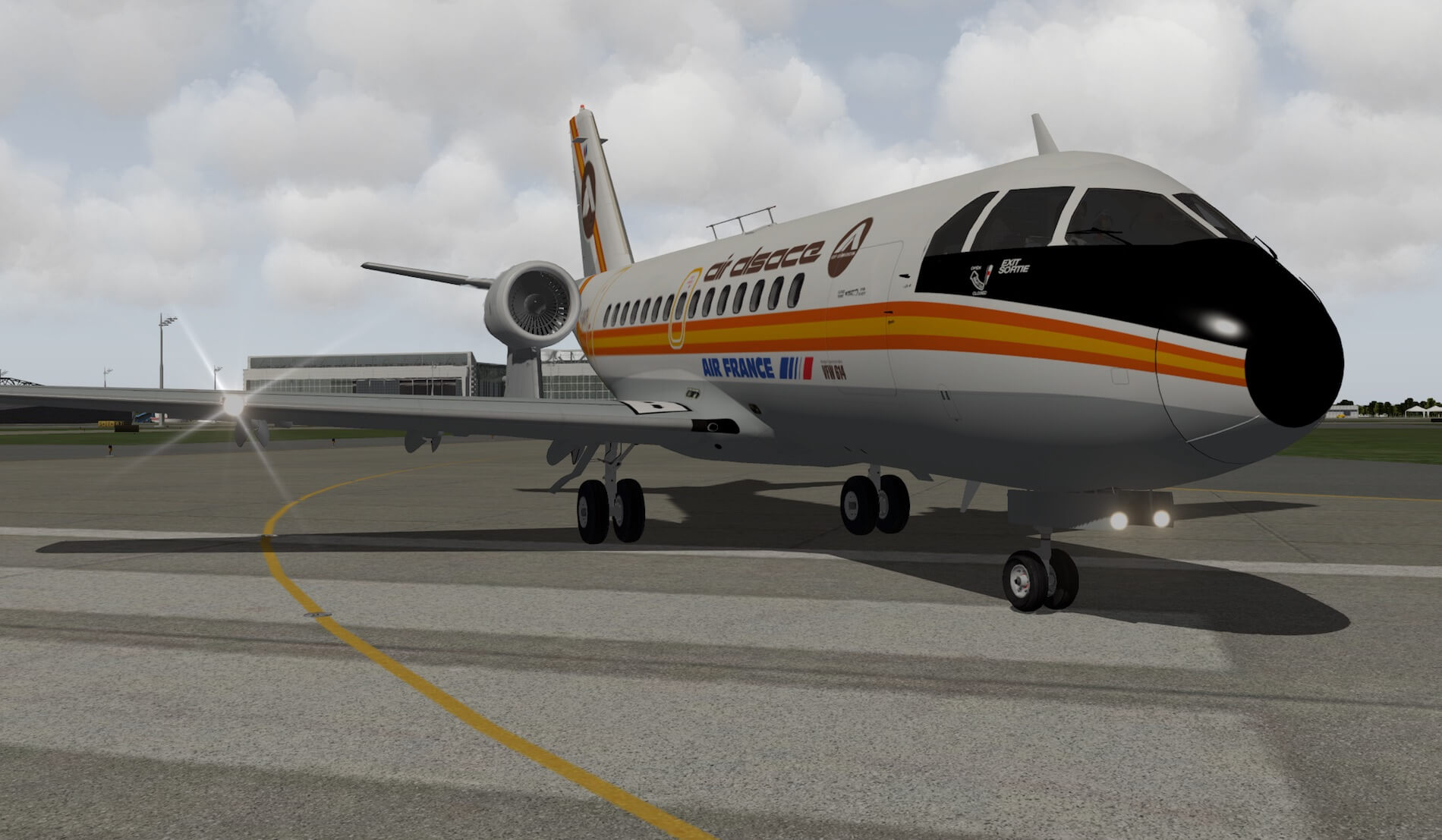
– Air Alsace (old French airline, was based in Colmar-Houssen)
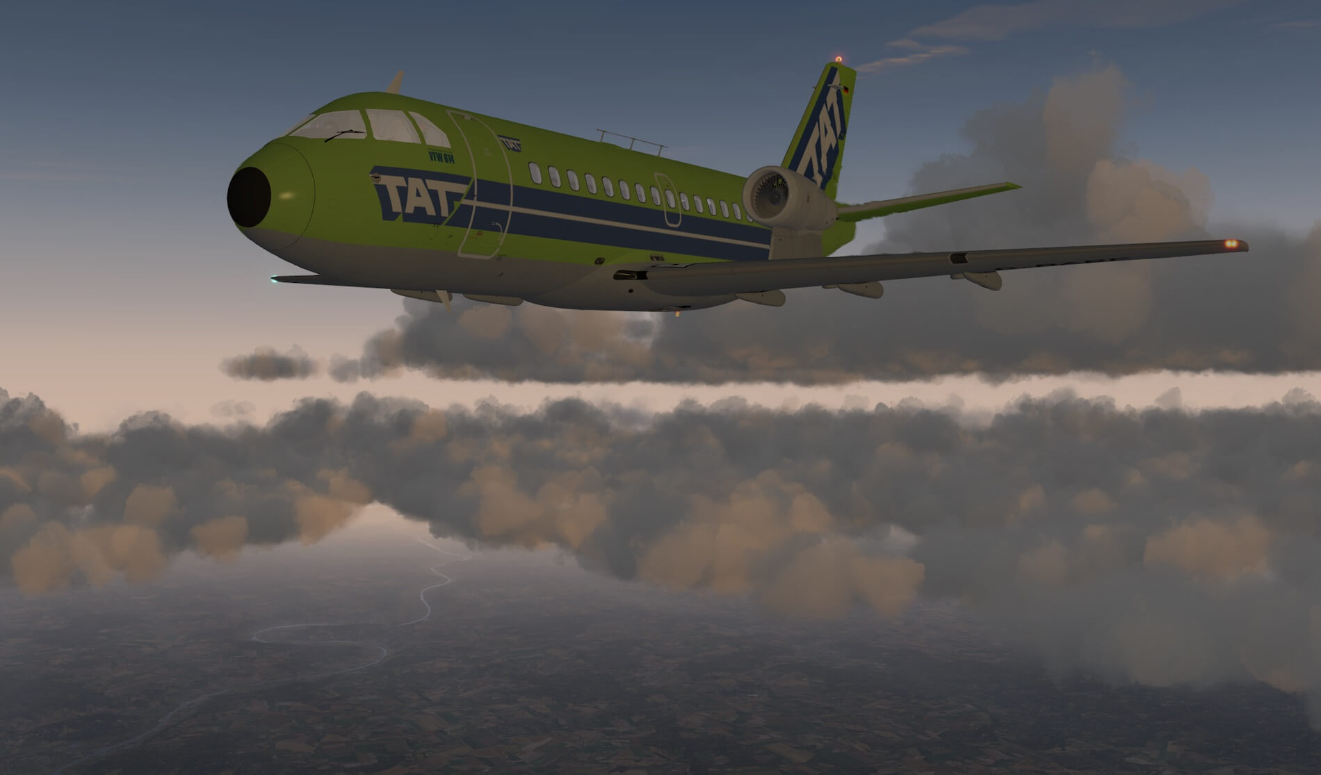
As far as I know and checked, what I miss and not such a big deal, is a paint kit, but I’m quite sure this will come soon although besides factory liveries (not included), no other airlines ever flew this VFW 614. While searching the Internet, I found at the VFW614 German website at least two additional factory liveries with a red and yellow fuselage strip and a blue Fokker-VFW logo on the tail. See the photo below. Want to know all VFW614 models that where build? Then you must check out this link.


Time to check out how easy or perhaps how complex and difficult this aircraft flies.
First Test Flight | VOR, HDG etc.
Introduction
To get an impression of the modeled VFW 614, I decided to make the first test flight from EDDM (Franz Josef Strauss International Airport) to EDDL (Dusseldorf Airport). It will turn out to be a flight not using the build in VFW INS.
Professionally I was familiar with the Fokker F28 and although the VFW 614 isn’t the same, many cockpit controls and indications are similar or close related to each other, but I found it useful to use the quick start manual as a guide to find my way quickly in the modeled 3D cockpit.
I prefer to start the VFW 614 with a cold and dark situation since it gives me the best way to pick up the controls and belonging indications. It will take a longer time to find my way in the cockpit then when you start with engines running, but starting the sim and the VFW 614 with engines running is in my opinion not realistic. Having a button that powers up the aircraft complexity without engines running is, knowing how we did it in real, a much more realistic option.
Before I forget it; the checklist. This is an out of sight with having all these authentic manuals and no, the checklist isn’t included in the quick start manual. You can find the checklist in the non-approved handbook starting in section 1.7.3 (Preflight Check Cockpit) pages 001 till and including 008. Then, you continue with section 1.7.4. (Normal Operating Procedures) pages 001 till and including 007.
Quick Start Procedures
That said, I start powering up the VFW 614 via the quick start guide on page 31 (Quick Start with aircraft Cold and Dark) till and including page 39. Keep in mind that you have the correct “quick start guide” version that belongs to aircraft package version 1.4.
Once I’ve started the engines by following Peters Aircraft quick start guide, I go back to page 19 which is the “quick start with engines running”. Now it feels logic to me since I’ve followed the necessary steps to power up the aircraft including engine start.
Some notes/remarks
A small note for you (see also page 32 of the quick start manual); the HYD E-PUMP switch has three positions namely MAN (backward) – OFF (middle) – RUD (forward). When the manual says in the ON position, it means the MAN (manual) switch position. Before you know, you’ve switched it in RUD!
I’ve finished my quick start section “engines running”, but hold on, I still need to close the entrance door. Oh, oh, I should have done this before. I know, my fault! Anyway, by default, the entrance-, cockpit- and lavatory doors aren’t operational. To get these doors OPEN/CLOSE, you need to assign either keyboard keys or buttons on your joystick and/or throttle unit. Assigning joystick buttons to the sim for door control is described in the quick start guide.
Starting the Test Flight
Now it’s time to start with my first flight impressions. I decided to make a flight with a planned cruising altitude of around FL180. Further on, I’m going to fly the VFW 614 first by hand, but later once at cruising altitude, testing the same with the AP connected in different modes. With PITCH and AILERON trim assigned to my joystick, I found out that flying the VFW 614 is easy although also a little bit nervous.
When you touch the controls, the aircraft responds immediately while I would expect that due to the aircraft mass, it would take some time before something happens and that the aircraft responds accordingly with pitch, roll or yaw. But as with many other aircraft, judging about the real aircraft behavior is difficult for me since I’ve never flown this aircraft. That said, keep monitoring your roll and pitch constantly (when flying by hand) since before you know, the aircraft drifts away from your intended altitude or heading.
Pitch seems to me less effective, but on the other hand, it’s then not going up and down like a roller-coaster. Once I’ve reach FL180, I level off, trim and see what happens for a while. With real weather active, it seems quite stable thus it’s time to connect the AP (Auto Pilot) and I warn you already that you shouldn’t expect big AP wonders of this aircraft. This has nothing to do with the programming, but this has to do with the limited AP functions/basics compared to modern commercial Auto Flight system of these days.


Ok, connecting the AP is done via the switch on the AP Control Panel, located on the pedestal. Select the switch to the AP position, but keep in mind, I have yet no AP mode selected on the AP/FD1 (2) Mode Control Panel (MCP). By the way, the glareshield panel has a left-hand and right-hand MCP with in-between the two COMM/NAV panels and the ENG and APU FIRE control handles.
Just before selecting HDG mode, I first align the HDG bug on the HSI on the heading I’m flying. But there’s something else you need to keep in mind and that’s when you set the AP switch to ON, automatically PITCH trim is taken over by the AP thus manual pitch trimming assigned via your joystick is no longer working, at least, that’s the idea I have and you can see this happening too with the pitch trim wheel. So, you need, see the quick start manual too, assign via the joystick also buttons for AP PITCH UP/DOWN.
Anyway, I faced a couple of times an issue – not sure if it’s an issue- that is, when I set the AP switch to ON, I could engage the HDG mode, but not for example the ALT HLD mode. Switching the AP switch back to OFF and ON solved this issue. Most likely the issue isn’t a problem. No, it’s perhaps because the PITCH TRIM wheel on the pedestal, subpanel AP Control Panel, isn’t in the middle position which is a requirement to engage the ALT HLD mode, so this is a good moment to think about assigning either a keyboard key or joystick button to Autopilot/Autopilot_pitch_synch. By the way, with the AP connected, you’ll see the AP trim positions on the indicator above the standby horizon (captains instrument panel).


Once I’ve set the AP to maintain a certain HDG and to ALT HLD, it’s time to check what else is possible. It must be said that it would be a good idea when Peter includes with future updates also a tutorial. Right now, the quick start manual doesn’t offer all the information a simmer may expect and I can imagine that simmers won’t quickly read the authentic manuals. I noticed, unless I missed this option, that you can’t let the flight control yoke/wheel disappear.
You may say ….. but this isn’t realistic. The problem is that you don’t have full sight on your HSI and ADI, especially your HSI. But there’s help on the way to enable/disable this flight control wheel/yoke. According to Peter “it listens to the standard X-Plane command Operation/Toggle yoke visibility as documented on page 9 of the Quick Start manual. It affects the onside yoke only. So, when you are flying as F/O, it’s the right seat yoke.”
I immediately tried to find it out and yes, after assigning the right X-Plane command, I’m now able to get the yoke out of view and having access to my main flight instruments during flight. Yes, I know what you think … some developers have such an option by clicking the yoke itself or via a popup menu, packed together with a plugin. Anyway, this is the way it works with the VFW 614.
Next on my to-do-list is tuning for a VOR station. So once more before I continue with this paragraph; my aircraft is in the following situation:
– Flying at FL180,
– AP engaged in the modes HDG and ALT HLD
– No F/D (Flight Director) selected on the Mode Control Panel.
After I tuned for a close-by VOR station, you see immediately in the HSI the distance – if the signal is strong enough and the station is not too far away and the station has DME too – to go and the HSI needle will become alive. Adjust the needle till it’s pointing TO the station and the deviation needle is in line.
Next click on the Mode Control Panel the LAT NAV button and when everything goes well, the AP will now steer towards the VOR station and leaving the HDG mode behind, but don’t forget to line up the deviation needle several times while flying to the VOR station else you won’t end up passing over the VOR station. A note must be made that NAV 1 is used for AP control while you can set another frequency for NAV 2. Both NAV 1 and NAV 2 needles direct to the radio station when a signal is received, and it can be seen on the RMIs and on the F/O HSI for NAV 2.
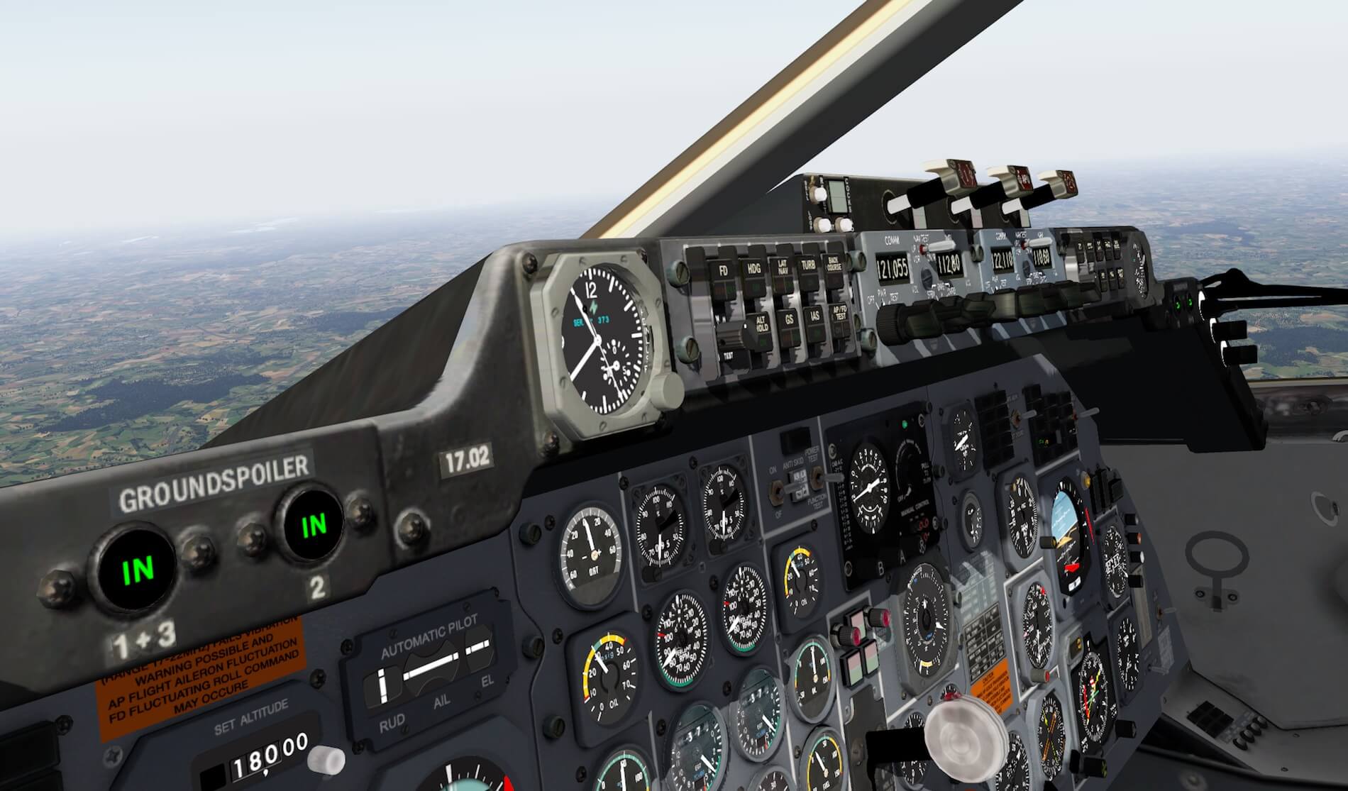
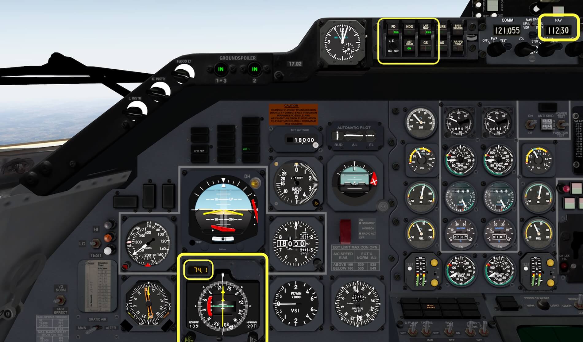
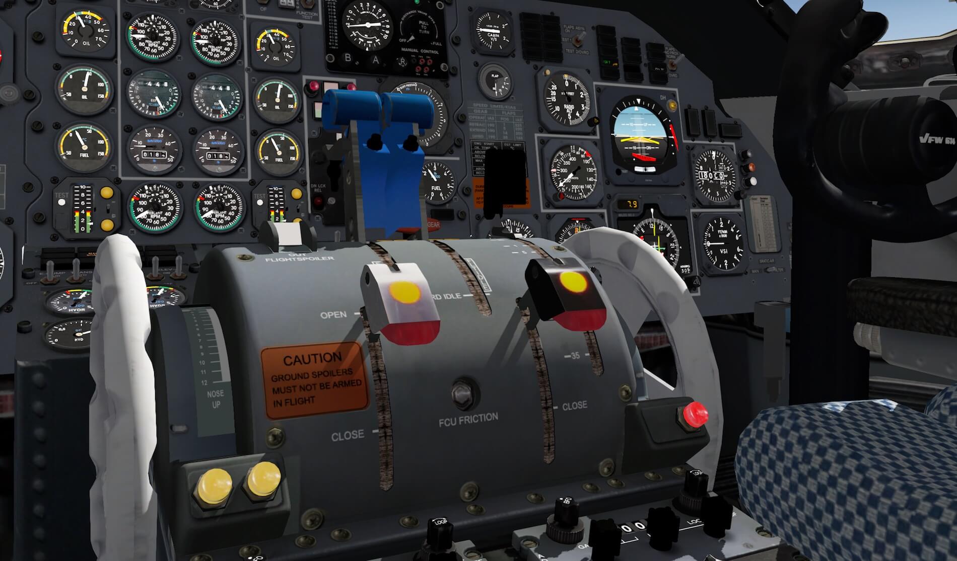
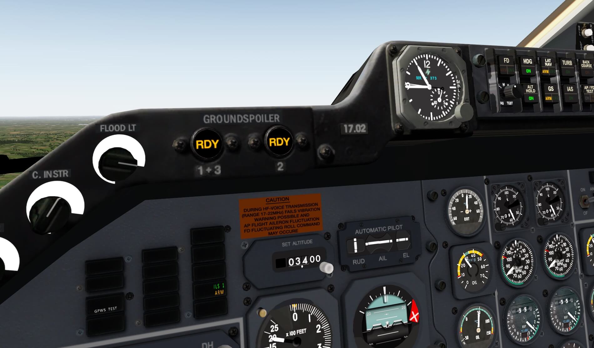
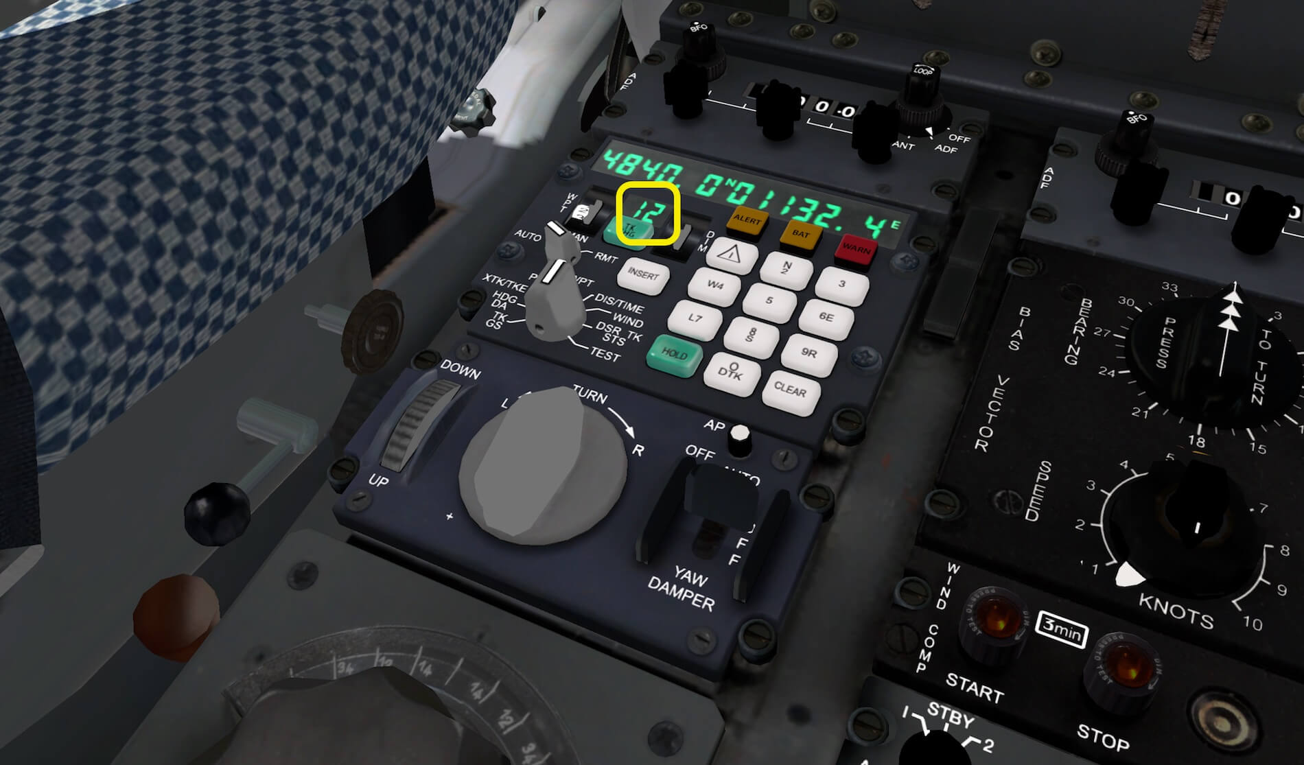
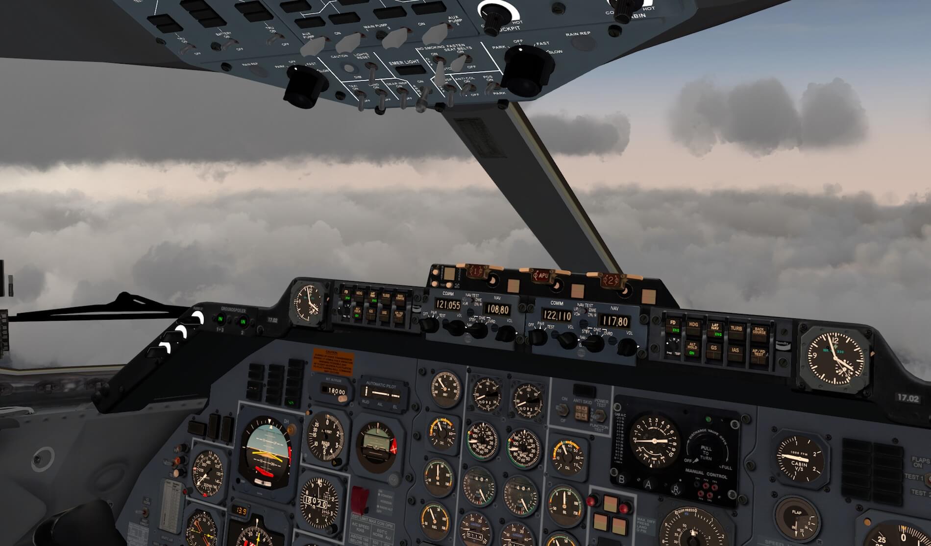
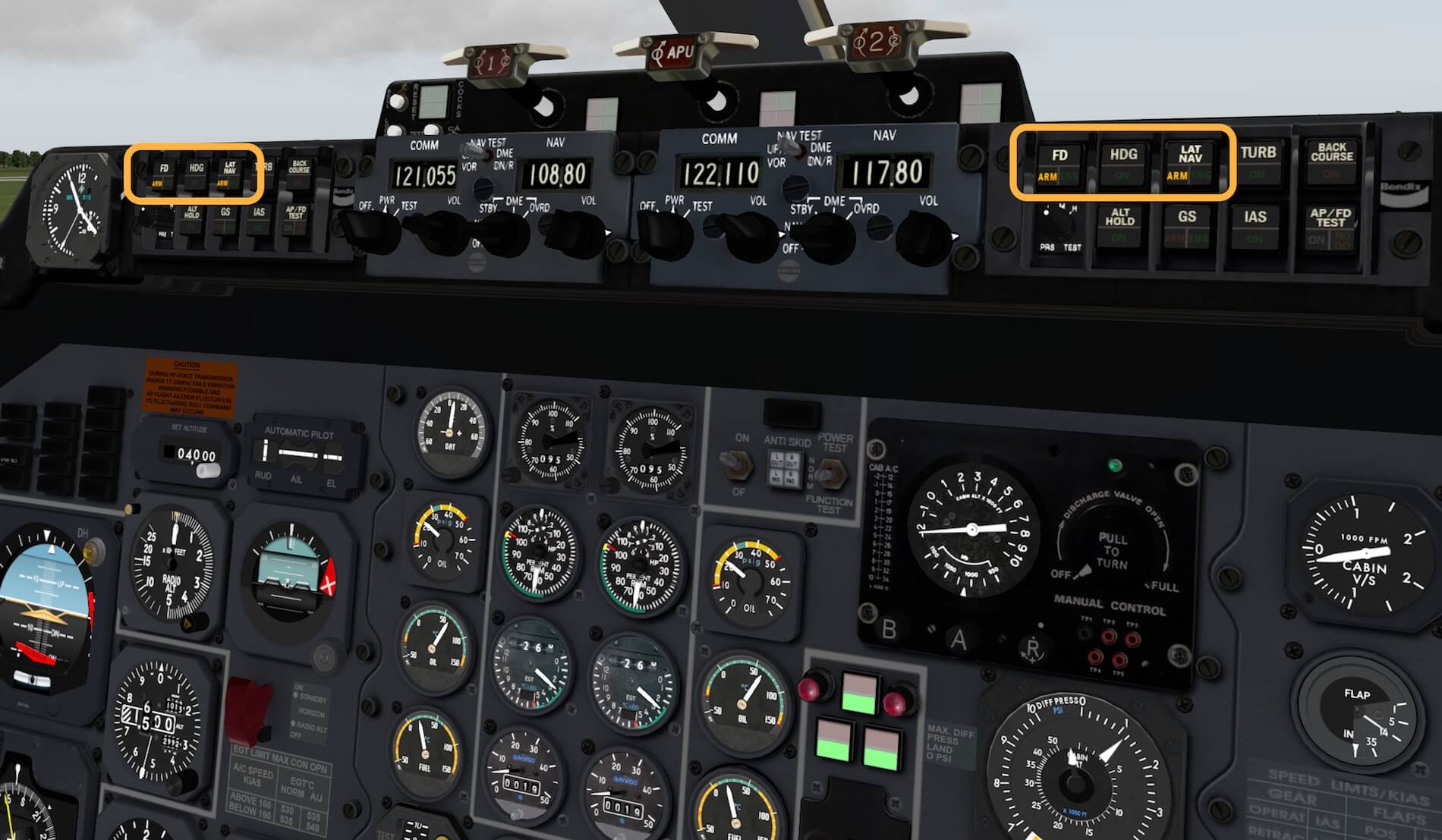
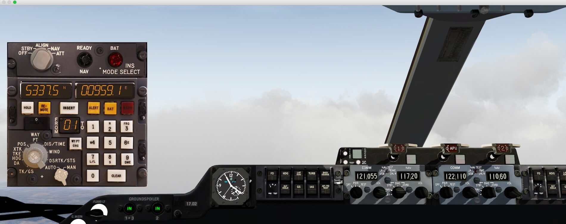
Although Peter promised me to change the following in the quick start manual, I would like to highlight this right here. It deals with adjusting the COM and NAV frequencies. At first sight, it feels odd and even I was confused by the double set of arrows, but once you know, it’s easy. See for the following explanation as well as the colored squares on the screenshot below.

Adjusting the COMM and/or NAV frequency is different then you’re used with other aircraft. Below the COMM and NAV frequency indicators you’ll see in total 4 knobs. The two left knobs are for adjusting the COMM frequency while the two right hand knobs are for NAV. Let me first focus on the COMM frequency and their knobs.
With the left hand COMM knob you change the value in x Mhz increments while with the right hand COMM knob you change the value in x Khz increments. The same applies for the NAV frequency with its knobs. Thus …… with the left hand NAV knob you change the value in x Mhz increments while with the right hand NAV knob you change the value in x Khz increments. In the above screenshot, you can see that the COMM 1 section is marked with red squares while the NAV 1 section is marked yellow squares. I hope this clarifies how to change the Mhz and Khz increments for the COMM and NAV. The above description is the same for the COMM 2 / NAV 2 panel.
I’ve been flying around EDDM so I didn’t come any further towards EDDL, but that doesn’t matter. I had the time to test the aircraft and I think it’s now time to go back to EDDM.
With my VOR tuned for Munich (112.30), I plan to land – under VFR rules – manually and see how that goes. Flying from VOR or NDB to an airport, in this case EDDM, is easy. The descent and approach for a landing on EDDM runway 26R is, due to the CAVOK weather conditions I created, not difficult although I must say that at lower speeds with FLAPS extended, the VFW 614 is a little nervous to keep the aircraft level. If this is as with the real VFW 614, is something I don’t know.
Ho ho, hold on.
Before starting with the EDDM approach, should I not write something about the modeled 3D cockpit and virtual cabin? Yes, I think that’s what you all expect, so lets go for it. Just a small note regarding the ALT ALERT aural message. When you start you descent – it’s also applicable during climb – and the ALT selector on the main instrument panel is different then you altitude intensions, you get an annoying ALT ALERT aural message indicating that your altitude is changing – climbing or descending – from the selected one. No problem, just select a new altitude that’s higher or lower then your current and the busser is gone.
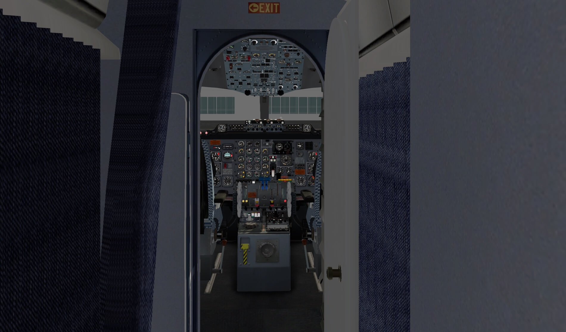
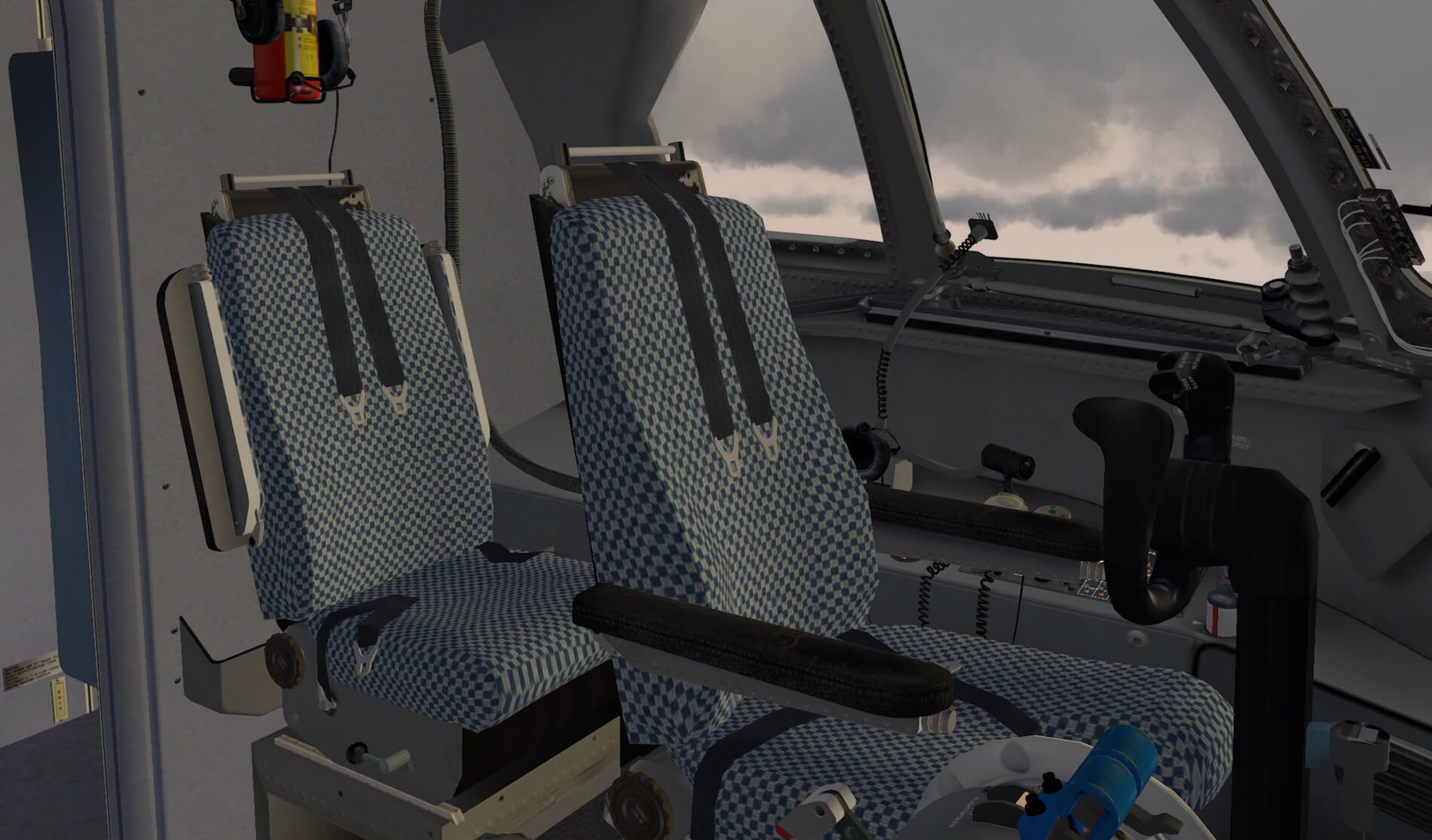
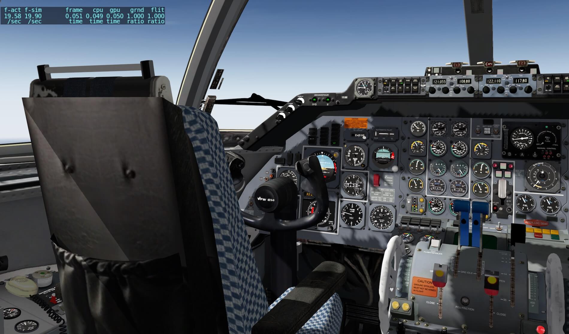
Cockpit Impression
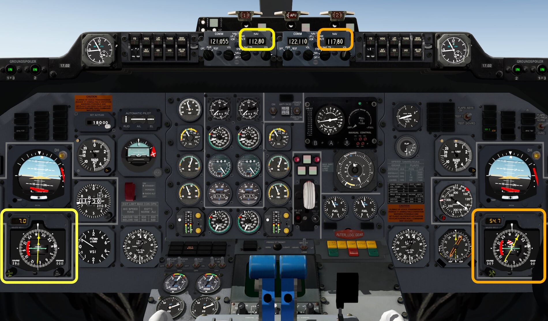
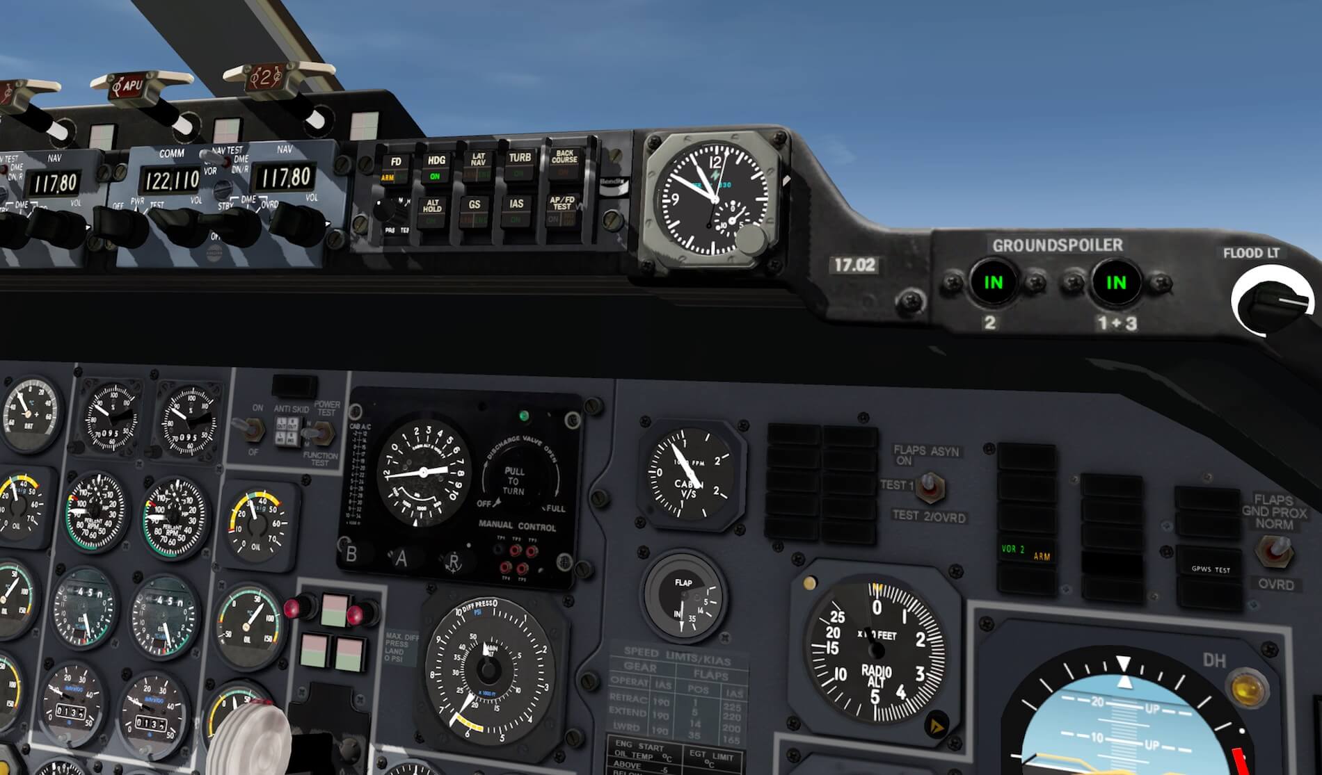
The modeled 3D cockpit gives you perhaps a feeling of …. unorganized panels, no structure, different panel colors and so on, however, that was the reality. In the years, the VFW 614 was made. In those days, I worked on the Dutch Fokker F-28 and the old Douglas DC-9 aircraft. Even the Fokker F-28 had also different colored sub panels on the overhead panel and glareshield. So basically, the way this VFW 614 3D cockpit is modeled is as it was in those days. As far as I’ve been informed by Peters Aircraft, he made many photos of a real VFW 614.
That said, the 3D modeling could and should be based on real photos, or even better, using real photo material could be a part of the 3D cockpit panels and objects. But I miss something during my first panel impression and that’s reality, that’s the real look and feel. For example, … the overhead panel. Although the sub panels look good to me, the panel texture has no dynamic, it feels one grey flat panel without any weathering or used spots, without scratches.
As it is, it’s not realistic. Even when you try to be gentle with a cockpit, the panels- and sub-panels are always the first places that will get scratches, dirty spots or weathering. Now it feels like a cartoon … the construction panels like the main instrument panel, the overhead panel etc. have no depth!


On the other hand, when you look from certain angles along the main instrument panel, side panels, overhead panel, pedestal and so on, you can see a 3D effect of the indicators, switches, lamp units etc. and it’s all razor sharp although it must be said that no NML file are used in the cockpit.
Some parts in the 3D cockpit look to my opinion a little too new, or if you wish, hardly used. I talked about this, the same which is applicable for the external aircraft, with Peter why it all looks so new besides a couple of dirty spots, and that no weathering is included. Peter told me that for example the 3D cockpit is based on a Luftwaffe aircraft which were kept as clean as possible while the flight crew tried to keep the cockpit as new as possible.
Long story short; it’s also the way Peter prefers to make/see his own aircraft. Trying to be objective, a cockpit that is old, is never new. That said, such an old cockpit will have all over the places wear. Now it’s only a matter if the developer wants to implement this wear and if he’s capable to do.


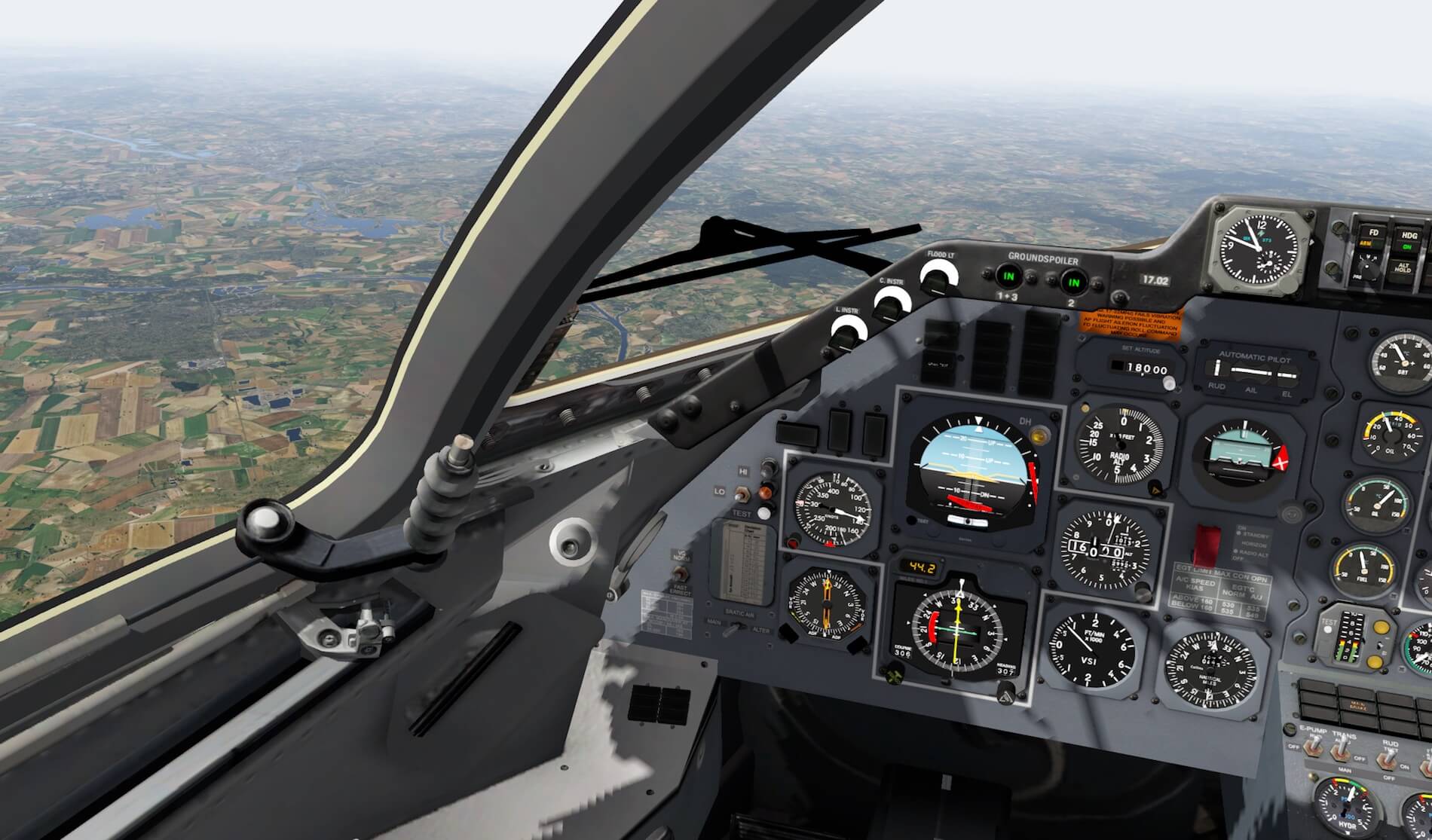
What else more ….. as far as I’ve seen and tested, the 3D cockpit does offer one sliding window, but that’s only on the captain’s side however, this isn’t modeled so you can’t open/close it.
Overall, I think there’s still some work to do to give this 3D cockpit a more realistic look and to get rid of the cartoonish look and feel of several panels. Since I’ve seen many other well modeled realistic looking 3D cockpits, I’m sure the 3D cockpit modeler and graphical artist can give the current cockpit a face lift.
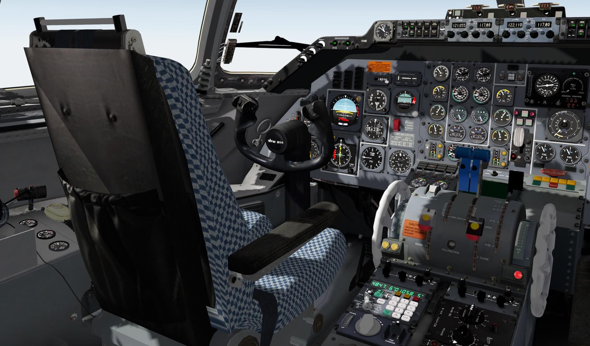
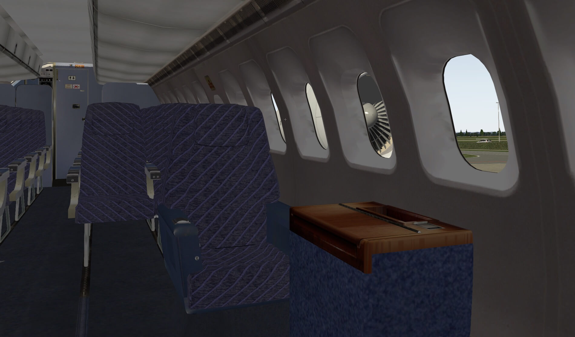
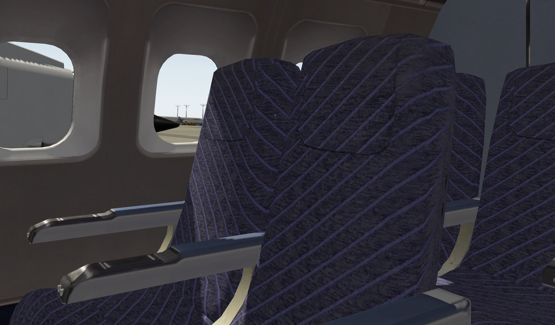
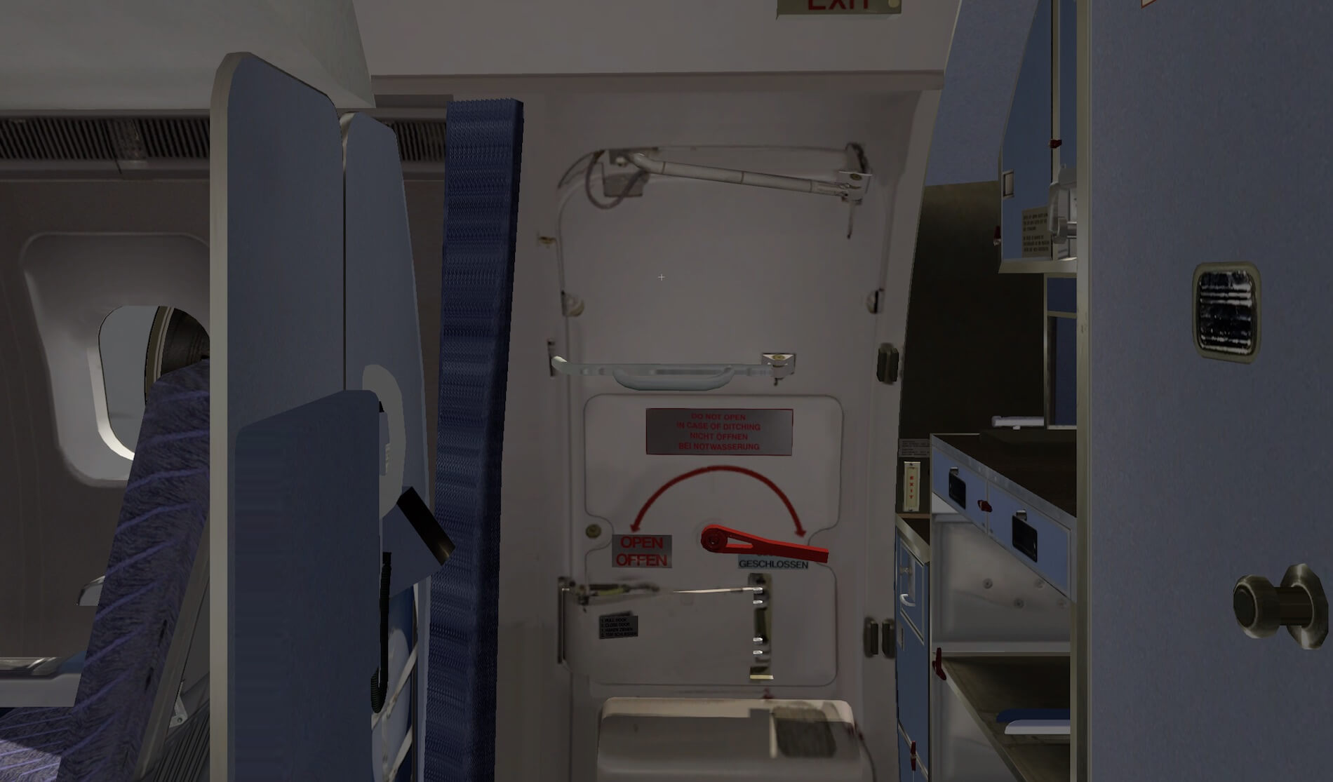
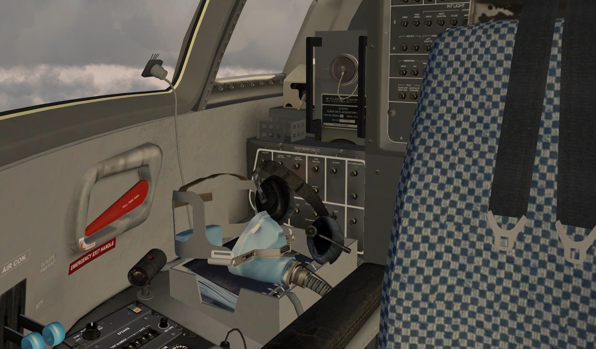
Passenger Cabin Look and Feel
I’m pleased with the way the virtual cabin is modeled. Some like it, some aren’t interested in a virtual cabin at all while some simmers like to take a window seat and enjoy the way the sidewalls, overhead bins, ceiling panels, passenger seats with their frame and carpet are modeled. As far as I can see, no real photo material is used in the cabin besides parts of the tables, galleys with trolleys, ovens etc.
I mentioned this before, the cockpit door is simulated as well as the lavatory door and entrance door with stair. Although these doors don’t “work” out of the box, after assigning either keyboard keys or joystick buttons to them, they become functional. And, exclusively for the VFW 614 model, is the animated foldable door which covers the main door from the inside, only when you stand clear of the door operating area.
Assigning all these animations to keyboard keys or joystick buttons is OK, but isn’t it an idea to create for example with a popup panel a way that simmers are able to select these animations. Another advantage of this is that simmers don’t need to follow all these “X-Plane assignment” steps. User friendly and a feature what is often used!
Continuation “Starting the Test Flight”
After a successful landing, I decide to make immediately a restart; set the FLAPS for takeoff and do the other necessary preparations to level off at 4000 feet. After being at 4000 feet, I make a left-hand circuit around 26R, but this time I enter the ILS frequency (108.70) and leave the AP OFF for the moment.


I connect the AP switch on the pedestal when I’m turning to final, followed by engaging the LAT NAV and G/S buttons. LAT NAV will engage while G/S shows me ARM (amber light). It’s possible that you can’t connect it while perhaps earlier in the flight it did work. No worries … help is on the way. I highlighted before that most likely you need to click the assigned button on your joystick or control wheel that syncs the pitch. So when you can’t connect for example ALT HOLD, click the joystick button or whatever you’ve assigned to, and you’re able to engage the ALT HOLD.
When the G/S signal is picked up, the G/S changes to ENGAGED (green) and the aircraft slowly descents along the flight path. But remember, also mentioned in the manual, you need to control during this descent the aircraft speed with the throttles yourself.
A good final approach speed with FULL FLAPS is approximately 130-110 knots. That said, I don’t do anything while the aircraft is following the ILS path. Don’t expect that you’ll see a AP FLARE mode. That’s something that doesn’t exist in the VFW 614.
Second Flight | Using VFW INS Configuration I
Working with VFW INS with CIVA plugin installed
Will I succeed in a flight by using the PA (Peters Aircraft) VFW INS or is it too complicated to use this build in INS. Since I own the CIVA INS, I think it’s a good idea to install the CIVA INS plugin, but I decided to use the VFW INS CDU as it is. As highlighted before, the funny thing is that when you have the CIVA plugin, and installed it in the aircraft plugins folder, that the VFW INS will be more or less behave as the CIVA INS. Ok, not completely, but the VFW INS has become a powerful and realistic INS CDU only because you’ve installed the CIVA INS plugin in the designated aircraft plugins folder.
That said, this second flight section deals with the operation and control of the VFW INS CDU, but with the CIVA INS plugin installed although I’m not using the popup CIVA CDU. What Peters Aircraft actually has done when you have the CIVA plugin installed in the designated folder, that it uses many of the CIVA add-on functionalities and implemented that behavior in the VFW INS. When you remove the CIVA plugin, then the VFW INS is basically a different look and feel of the default X-Plane FMS.
VFW INS Explanation
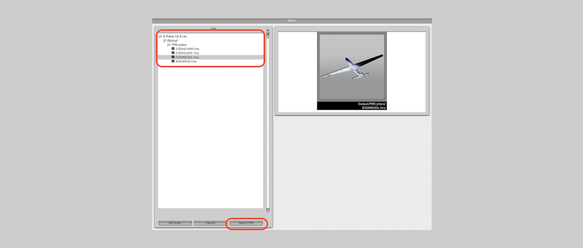
The following description and screenshots should give you a good idea how to “scroll” thru the different flight plans (if you have more then one installed), stored within your X-Plane Output/FMS Plans folder and having the CIVA plugin installed, but not using it. That you don’t want to use the CIVA INS popup could be because of many reasons. One of them is that you don’t like to have a popup window, as this is the way how the CIVA INS plugin is implemented in the VFW 614. Or perhaps you want to keep the VFW 614 aircraft as original as Peters Aircraft has had in mind, but using its own created VFW INS this time with many CIVA INS functionalities implemented.
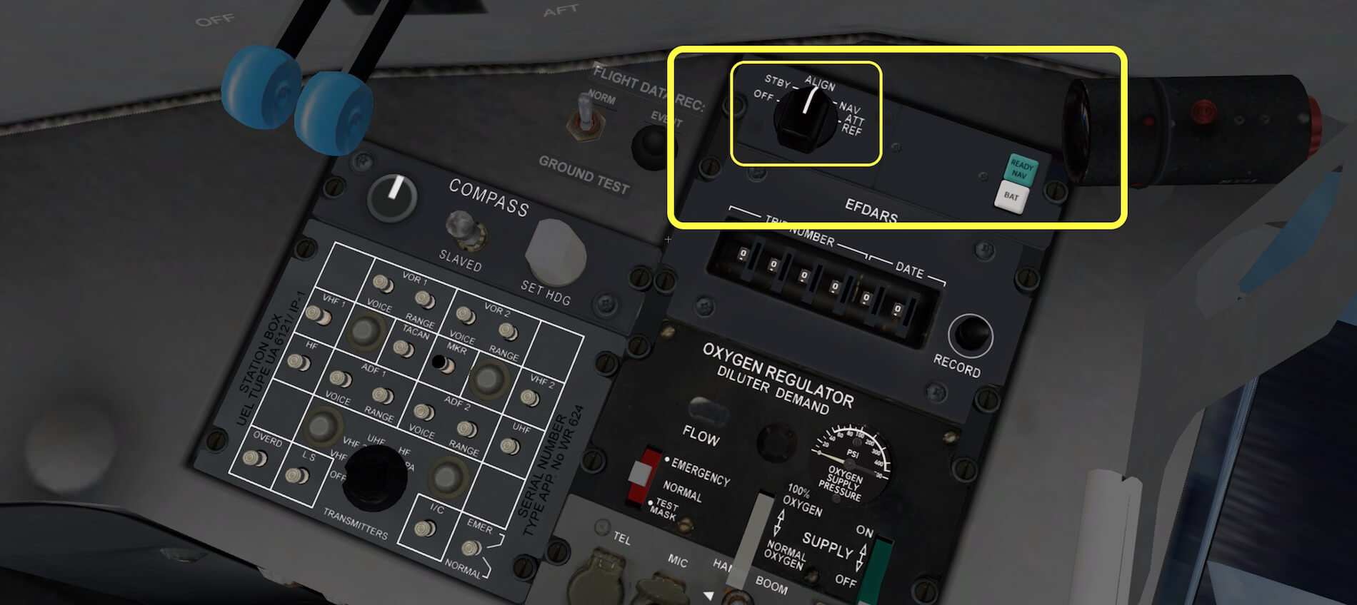
As you can see on the second screenshot with flight plan EDDMEDDL.FMS in view, scrolling thru the plans is done via a thumbwheel left of it (within the yellow square). I can’t see if the thumbwheel is simulated, but when you move you mouse pointer in this area, an UP or DOWN arrow appears. To save the flight plan, you click the INSERT button (amber square). Keep in mind that when you power up the aircraft from a cold and dark state, that to power up and thus to use the VFW INS unit, you need to select the selector switch on the MSU (Mode Selector Unit) to ALIGN and after ALIGN to NAV.
Just to keep you sharp …. as far as I’ve seen this is only applicable when you have the CIVA plugin installed. When you have no CIVA plugin installed, the VFW INS is right away electrically powered and thus functional the moment AC electrical power is applied to the aircraft.


Preparations and ….
First some words about how to connect the loaded flight plan to the Auto Pilot. I think I haven’t mentioned this before; the VFW 614 comes with a basic Auto Pilot, at least not as sophisticated as modern Airbus aircraft are, but for sure it doesn’t come with an Auto Throttle and/or Auto Thrust system.
Back to how to connect?
On the ground, you can click already the LAT NAV button on the MCP (Mode control Panel). ARM is illuminate in amber, but ARM is not yet ENGAGED, so how to do that? I clicked the TACAN button/light above the HSI (see also picture page 15 of the quick start guide). TACAN will appear in green while in the LAT NAV button I see a green ENG (engaged) light. Yes, I’m aware that the AP is still not ENGAGED, but for LAT NAV is set for flight.
When airborne, I connect the AP lever on the pedestal to ENGAGE and the VFW INS will connect to the AP and thus the aircraft will follow the flight plan. Keep in mind that the current pitch is maintained by the AP. Pitch angle can be changed by the PITCH TRIM wheel on the pedestal.
In Flight VFW INS Behavior
The whole flight plan looks like this:
1 EDDM 0 48.353800 11.786100
11 INPUD 0 48.667100 11.541500
11 UPALA 0 49.214400 11.221400
11 INBED 0 49.387600 10.941700
11 LOHRE 0 50.067000 9.486300
11 TEKTU 0 50.342900 9.136400
11 SOGMI 0 50.527500 8.899200
11 ARPEG 0 51.016600 8.306300
11 BADGO 0 51.096000 8.235700
11 ABILU 0 51.410100 7.954200
11 ADEMI 0 51.482600 7.888600
11 INBAX 0 51.454900 7.732100
11 DOMUX 0 51.419800 7.536400
1 EDDL 0 51.280900 6.757300
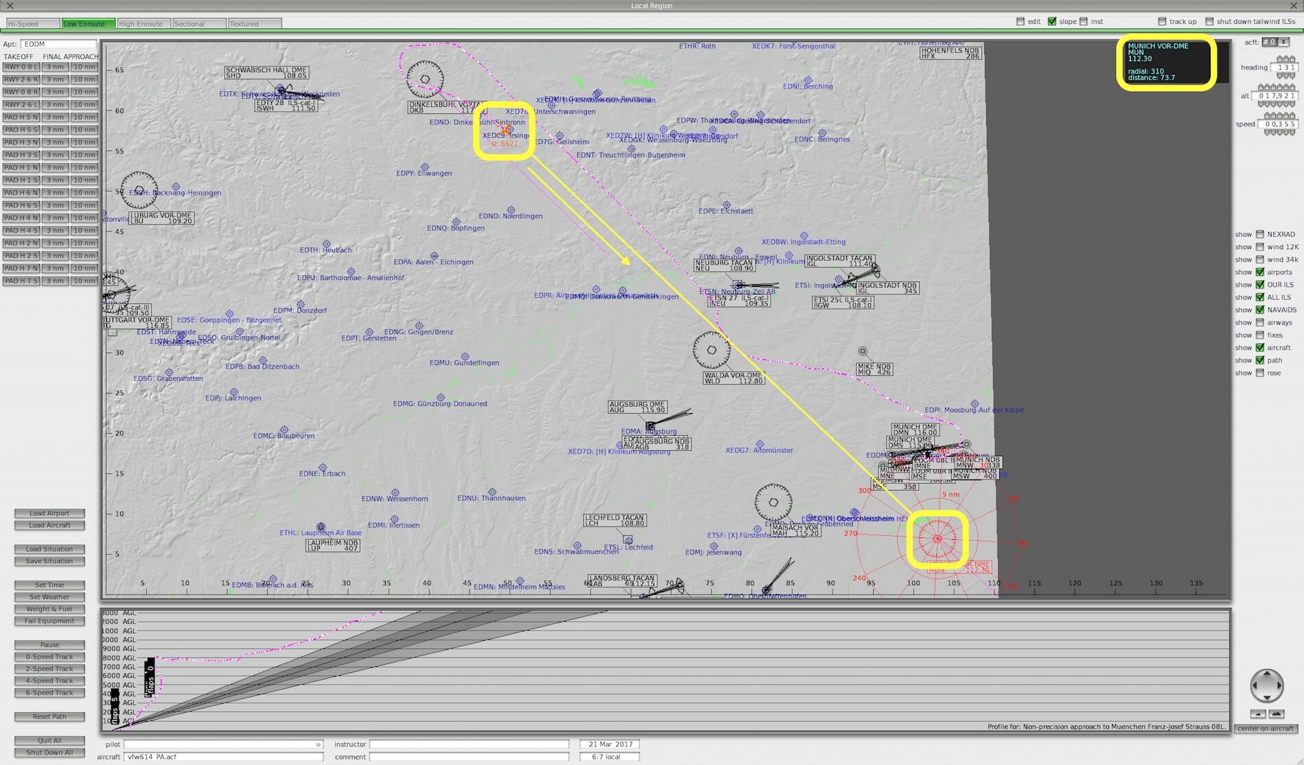
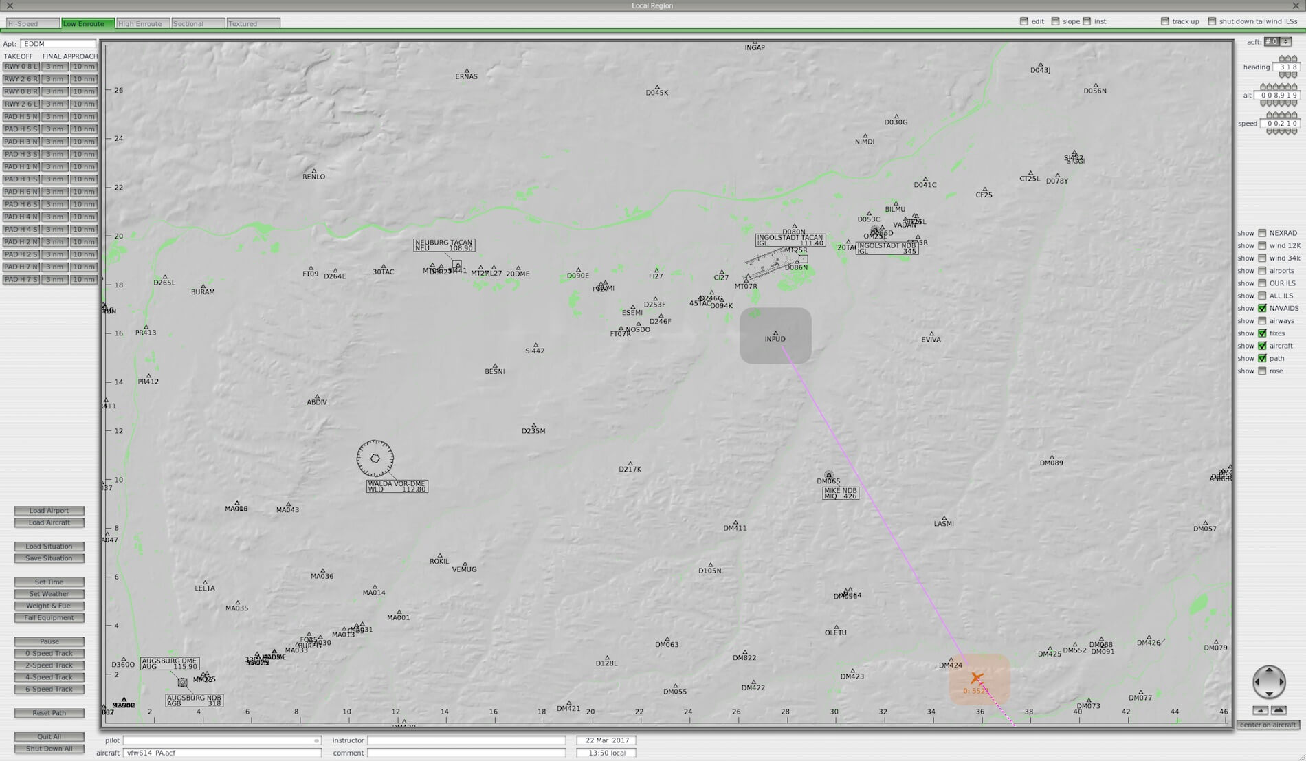
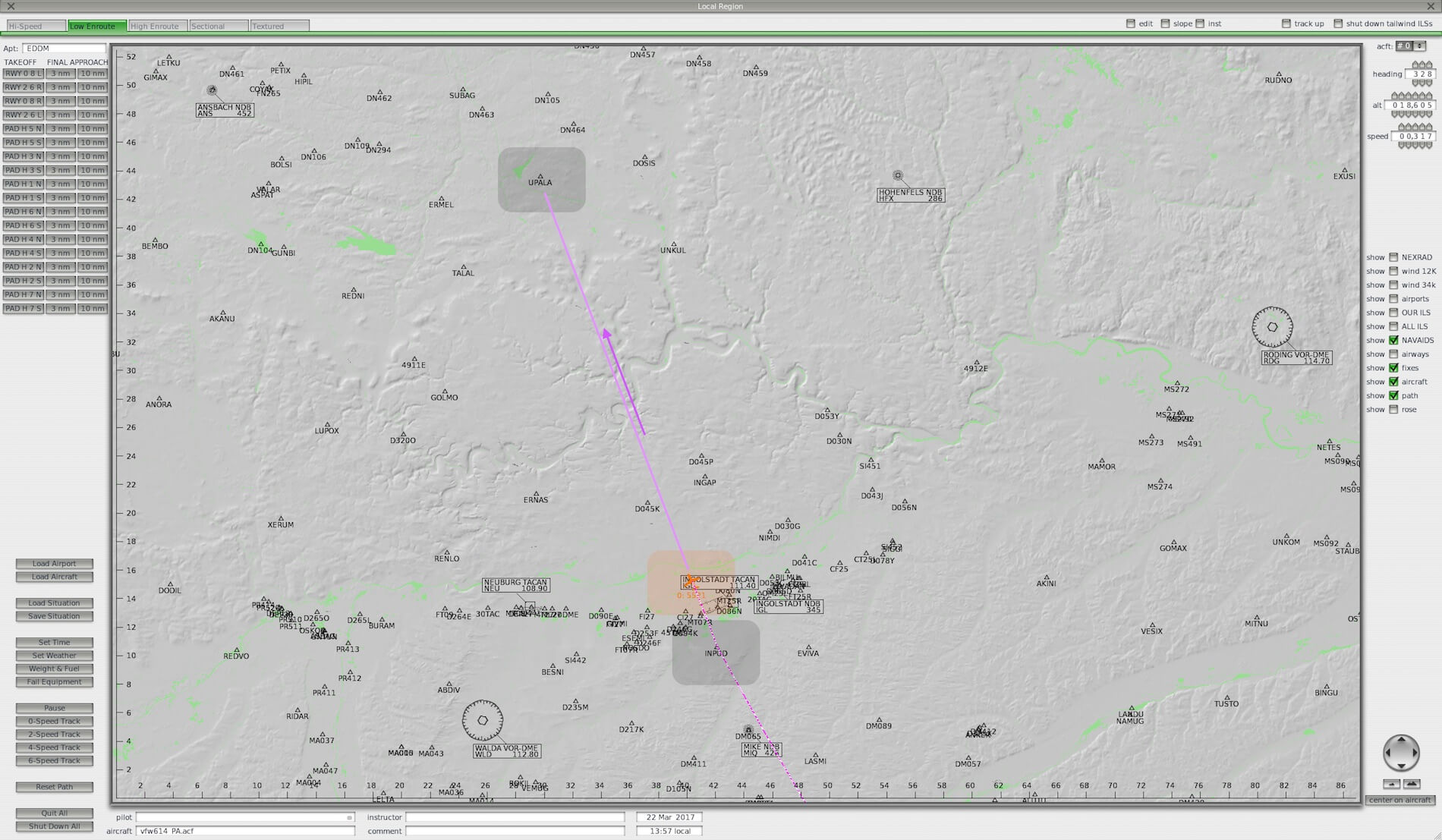
As you’ve noticed, I’ve highlighted two waypoints – INPUD and UPALA – for specific reason. In the screenshots below you’ll notice that I’ve made some screenshots of “where we fly to” and “how that looks at the VFW INS CDU”.


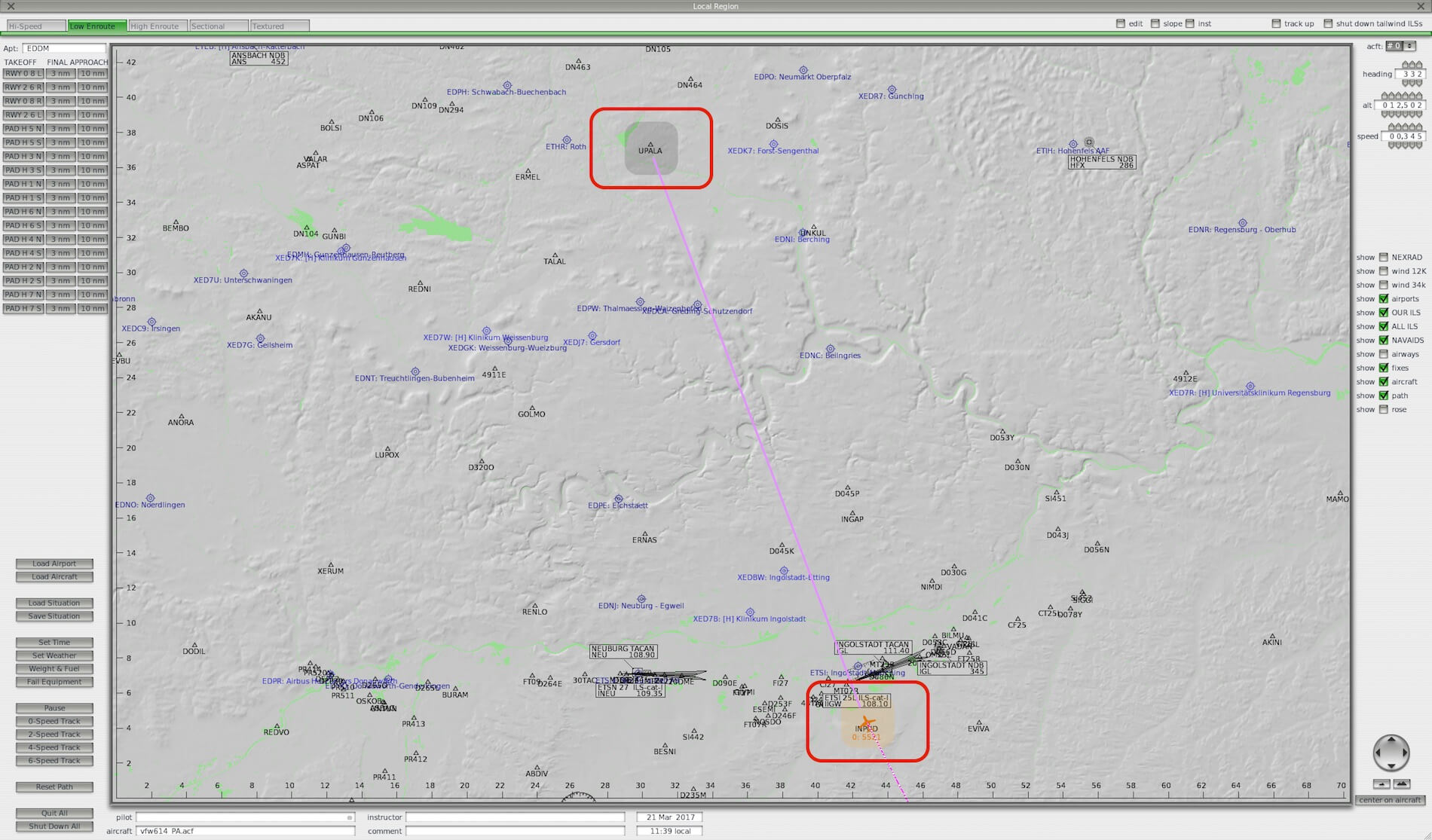

Right now, while flying to EDDL, the AP and FD are both engaged with the AP using the modes ALT HLD and LAT NAV modes. And as you have read before, navigation is taken care via the VFW INS. When using the VFW INS, you don’t have a map or something that visualizes where you are.
The old-fashioned HSI don’t offer you any visual map and therefore, you either need a chart from Germany or you connect an iPad or iPhone to X-Plane that offers you a ground map with you in position. When you own an Apple iOS device, the above visualization could be an option by using X-Mapper Pro app from MGJ Interactive. But what when you have no iOS device or you own an Android tablet?
Sorry, this app is not available for Android tablets/smartphones. In those cases, you need to print the complete flight plan via the exported Acrobat file, created via Online Flight Planning.
Hold on, one step back.
When you create the flight plan via Online Flight Planning, you save the flight plan with the “fms” extension, and added to this you also select for the Acrobat file. This gives you all the relevant flight plan information including all the waypoints and the distances to each station/waypoint.
But there’s another item I need to highlight and that’s finding out the right moment to start your descent. You can try and experiment when you should start your descent to EDDL. To catch the moment of the intended descent, we don’t have the help from FMS or any other sophisticated device, On the other hand, you can find all the relevant information at the IVAO Top of Descent calculation sheet.
With the above URL, I make my own calculations for the top of descent, the time I need to reach EDDL and the vertical speed needed. Most of this is with the AP engaged and the planned ILS approach.


Such a flight like this, not much different then the previous flight without VFW INS, is much more complex then flying an Airbus A320, A330 or A350, but neither less still interesting to do. In case you prefer not to use the VFW INS, you can always, whenever there are enough VOR or VORTAC stations on the ground, fly from VOR to VOR station, preferable those VOR/VORTAC stations with DME. Then, using only VOR and/or NDB stations, it is really the old-fashioned way pilots flew their aircraft in those days where there was no INS or IRS with FMS.
Frame Rate Impact
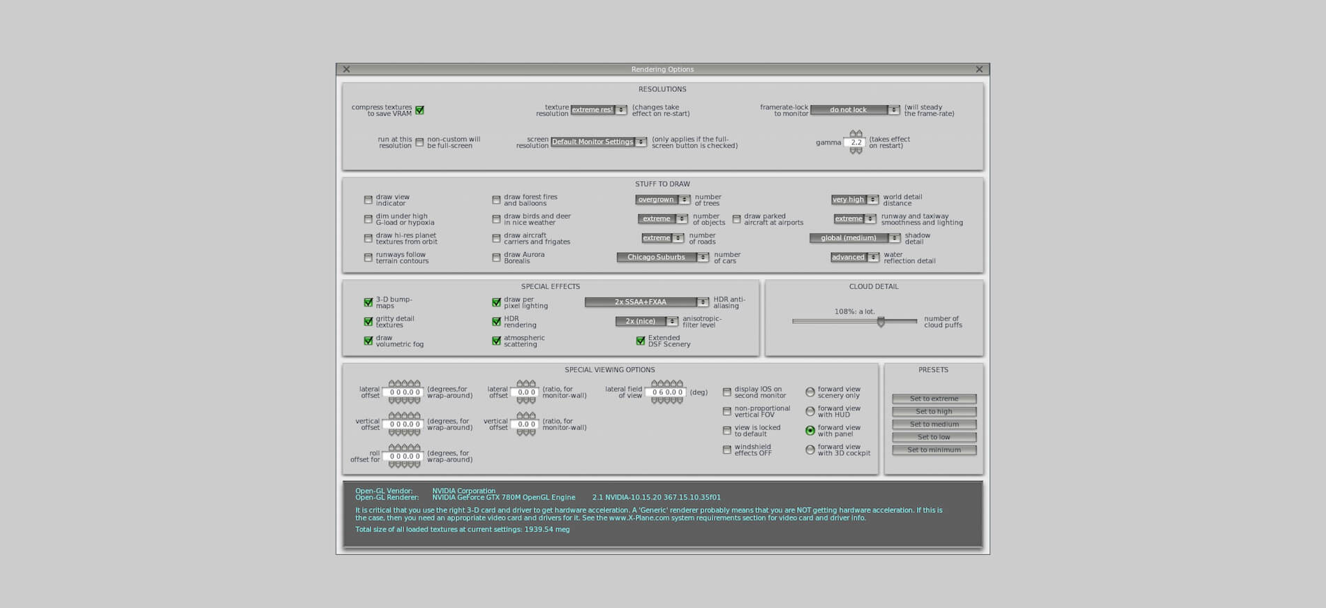
Oops, almost forgotten, but still an important item. Due to the overall type of instruments and the way it’s programmed, you shouldn’t have too much problems with getting normal frame rates. Without doubt the aircraft is frame rate friendly although I must be careful with this, but knowing my iMac hardware specifications, I can conclude that I always had at least 25-30 FPS. Some will say … that’s not something unique, but then you need to keep in mind my rendering options which are always set too extreme high. I’m also aware that my iMac is not the fastest iMac around there.

Third Flight | Using VFW INS Configuration II
Introduction
He, are you that flight simmer who prefers to use the default build in VFW INS as it is? Or are you the flight simmer who doesn’t want to spend another 10.00 USD for the CIVA INS add-on?
Yeah, I can imagine that and therefore, I will show in the following section how to load the EDDMEDDL.fms flight plan and how to interact with the CDU thus how to use it in flight as well as how to connect the build in VFW INS to the Auto Pilot. I can tell you already that since many functions are no longer available, it’s easier to understand the bare VFW INS CDU and how to operate. Ready, let’s go!
Some VFW INS notes
Normally you would enter your flight plan, as far as this is possible with the build in VFW INS, before you start the engines. So, now it’s the time to do this, but let me first highlight what’s working and what’s not. That I use the build in VFW INS CDU is because not everybody owns the payware CIVA INS. And I would like to add something to this paragraph that deals with how the VFW INS functions without the CIVA INS plugin installed.
What you know already, when you use a flight plan, it must have the “fms” extension and copied and paste into the X-Plane/Output/FMS Plans folder. You’re also aware that a flight plan can be created with either Simbrief Flight Planning or with the more simplistic, but still useful Online Flight Planning. An yes, many other online browser flight planners are available too.
Looking to the build in VFW INS, I’ve noticed that the following switches or buttons are functional although not sure if they are simulated:
– Selector switch AUTO – MAN – RMT (not explained in the guide page 14)
– Selector switch for all different readings (not explained in the guide page 14)
– INSERT button (no function)
– CLEAR button (sets the display too all 0s)
– HOLD button (HSI source for FMS)
– Display TRACK INDICATOR (opens the saved FMS flight plans folder)
It seems to me that the two selector switches have therefore no function. For sure this is the case with the large selector switch. You can rotate it, but the indications do not change.
VFW INS Explanation WITHOUT CIVA plugin
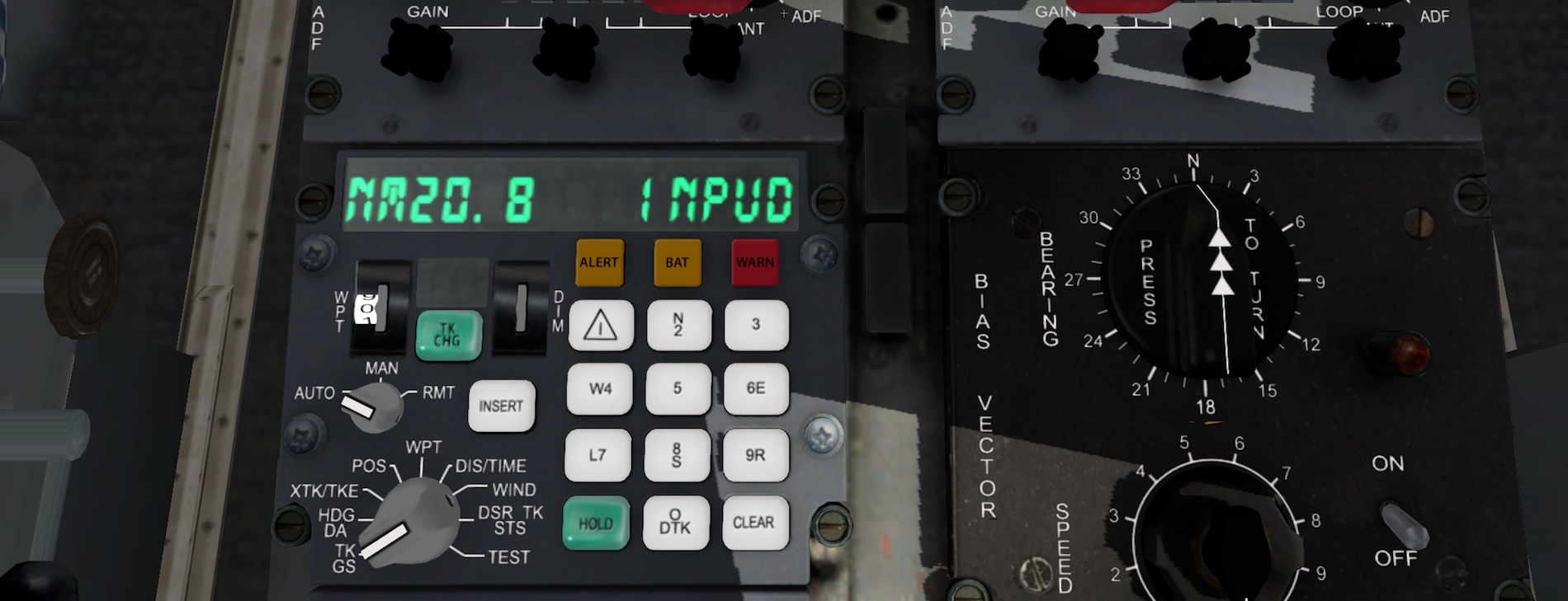
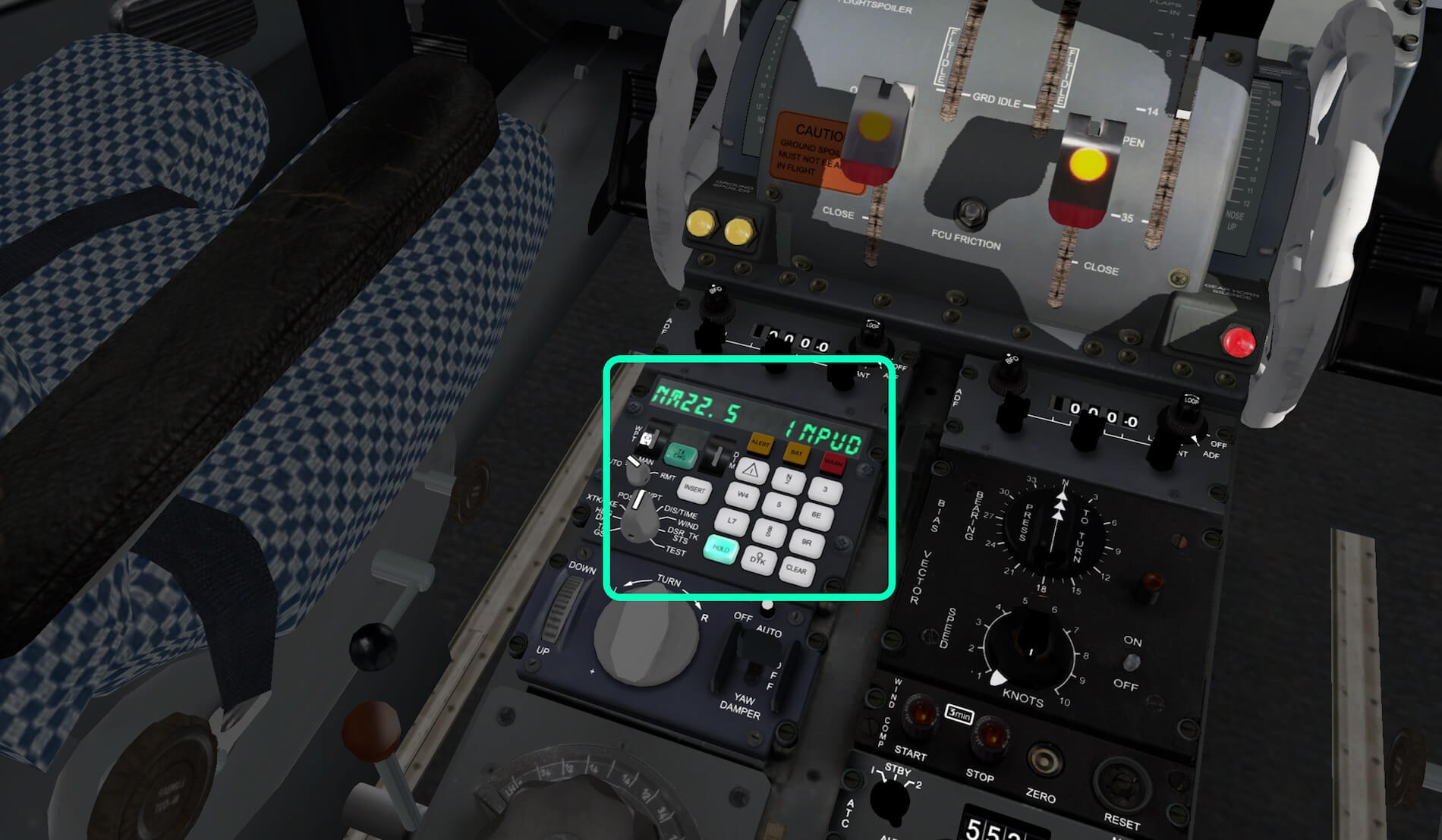
With AC (Alternate Current) POWER available, either via the external power or via the APU, the VFW INS display shows all 0s which is the same when you press the CLEAR button. The first screenshot shows you the MSU, however, the selector switch of this panel is still in OFF while the VFW INS is powered and up and running. Perhaps the MSU has in this situation no function while it has with the CIVA INS plugin installed.
Next I need to load my FMS flight plan.
I click the grey area above the green TK CHG button (see light green square in the screenshot). The available or stored X-Plane FMS flight plan window popups up. I select for this example EDDMEDDL.fms and click the OPEN FMS button. My VFW INS show now the first waypoint name and the distance to it (NM20.8 ….. INPUD).


And … Now in Flight?
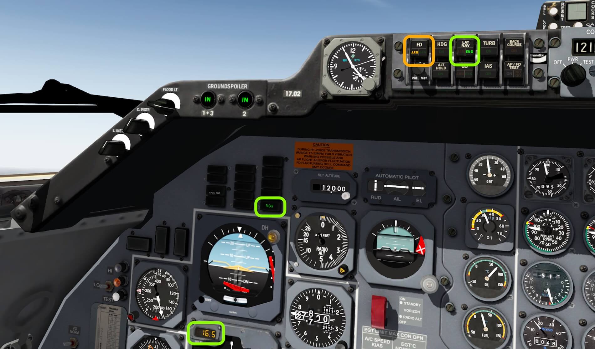
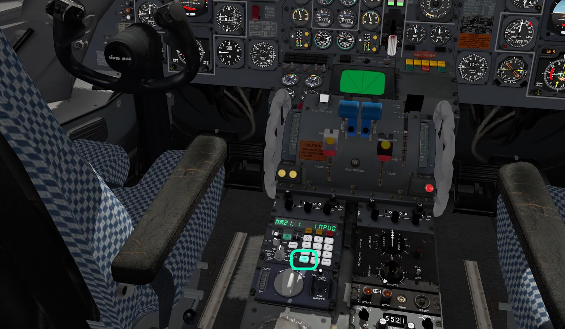
While I’m still on the ground, I ARM the LAT NAV (amber ARM) and click already the HOLD button on the VFW INS. This sets the FMS ready for the Auto Pilot although you can’t connect the AP selector yet. By the way, on the AP MCP I notice that within the LAT NAV button, a green ENG light has illuminated. Further on, I also set the FD which will be in ARM mode. As indicated in the quick start guide “HOLD button, if highlighted, tells the AP that the LAT NAV is connected to the INS system, not to VOR. It is recommended to activate LAT NAV and HOLD prior to take off, in conjunction with the FD. After take-off, you should engage the AP, before the system possibly looses track of the flight route.”
Ok, nice to know, but what can I do with the VFW INS in this case (remember …. no CIVA INS installed)? Honestly, not much. The VFW INS display shows you only the distance in NM to the next waypoint and the waypoint name. In that respect, it’s more user friendly then showing the latitude and longitude coordinates. That latter is more realistic, but that’s a different discussion. You’ll notice also that, mentioned before, that the large selector knob that allows you to select track, G/S, HDG, POS, PPOS and all the other positions, non of them do something. That said, the display can only show the distance to go to the next waypoint and the waypoint you’re flying to.
If you like it or not, that’s it, but it works. I selected the AP after climbing out of EDDM, and immediately the FMS, read INS, is connected to AP and the AP steers to the right heading for the first waypoint INPUD. And after that, waypoint UPALA etc. In other words, it works flawless. The following screenshots show you the first part of the flight using the build in VFW INS without anything else.


Meet the Old Fashioned CIVA INS
Introduction
This section is for those flight simmers who want to know a bit more about the operation of the INS unit in general. And, who have read the second and third test flights and seen the differences in VFW INS behavior and functionality, for those this section could be also interesting too.
The INS
The simulated INS (Inertial Navigation System) is a perfect companion for old-fashioned aircraft since, without this piece of hardware, navigation must be done with the help of VOR or NDB stations. In case you’re not familiar with VOR and/or NDB stations/beacons, I’ve added also the Wikipedia pages. Of course, many other website are available that offer you thorough background information about these navigation aids.
Delco Carousel was a popular INS-based navigation automation system for aircraft developed by Delco Electronics. Before the advent of sophisticated flight management systems, the Carousel allowed pilots to automate navigation of an aircraft along a series of waypoints that they entered via a control console in the cockpit. The Carousel used an INS as its position reference for navigation. Many aircraft were equipped with dual or triple Carousels for redundancy. The Delco Carousel derives its name from the fact that the inertial reference platform is in constant rotation as a technique to reduce drift and increase accuracy.
Basic Construction
Consider an accelerometer as an instrument that measures acceleration along a single axis.
Integrate the output once, and you have velocity. Integrate again, and you have position – or rather, change of position – along the accelerometer’s axis. If you know the direction of travel, you can deduce current position.
Inertial Navigation is simply a form of dead reckoning. You need to know the starting point. An Inertial Navigation device/system can’t find its initial position on the earth (it can find latitude, with difficulty, but not longitude).
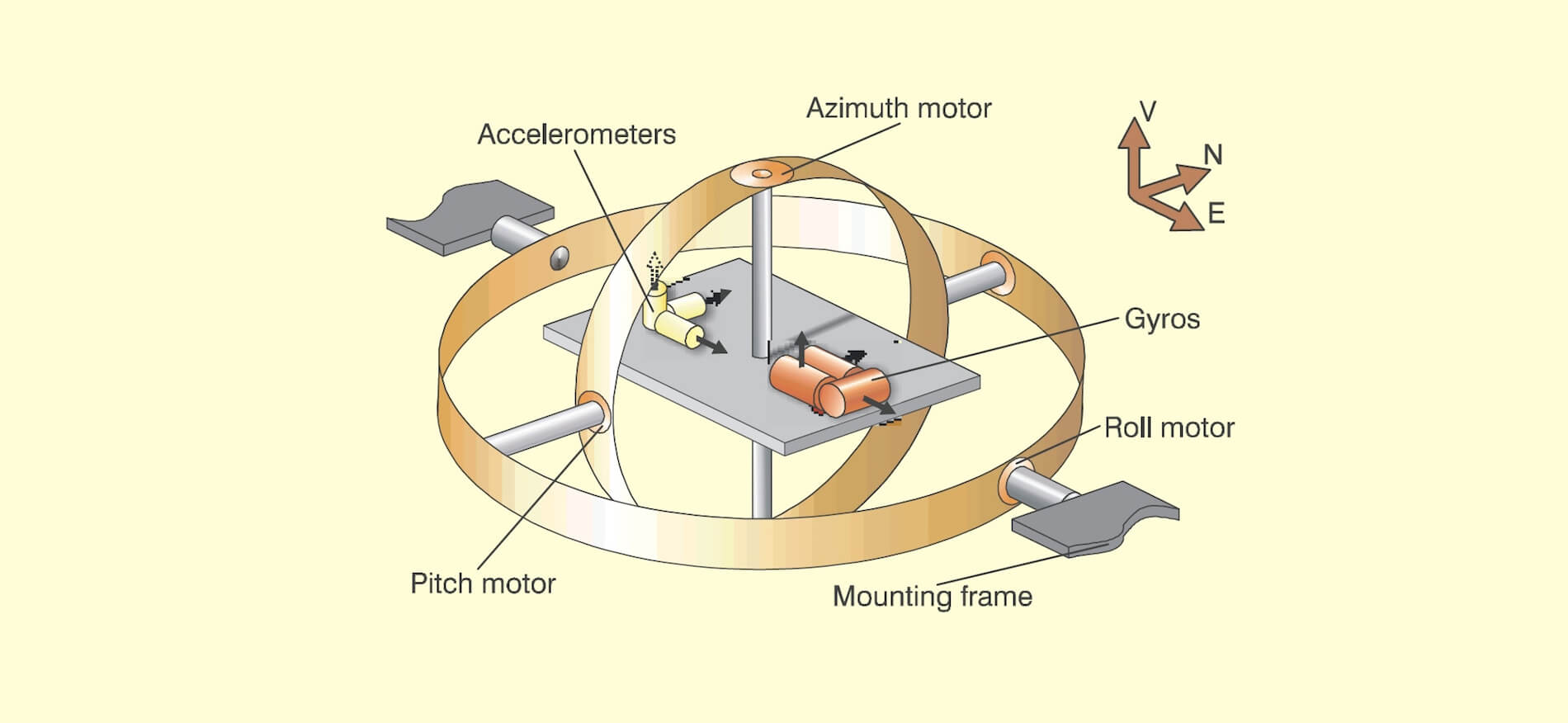
Take three accelerometers, with their sensing axes orthogonal. Arrange them so that their axes are aligned north south, east west, and vertical. To maintain this orientation when the vehicle maneuvers, the accelerometers are suspended in a set of three gimbals that are gyrostabilized to maintain the direction. Later we will be describing strapdown arrangements, but it always seems easier to explain the principles by starting with the gimbal model.
The gyros, similarly, are single axis devices, of a type known as integrating gyros – that is, they give an output proportional to the angle through which they have been rotated (about their input axes). The gyros are used as the sensing elements in null seeking servos, with the output of each gyro connected to a servomotor driving the appropriate gimbals, thus keeping the gimbal in a constant orientation in inertial space.
Integrating gyros also have what is called a `torquer’, a means of processing the input axis at a rate proportional to input current.

This combination forms a convenient means of cancelling out any drift errors in the gyro. The gimbals, as shown in the figure, (well, they may be there but they are not identified) have a bearing at each end. Each has a motor, built around one of the bearings, and at the other end a synchro.
No matter how the aircraft maneuvers, the innermost gimbal maintains its orientation in inertial space. The synchro on the innermost gimbal thus measures azimuth (or heading), the synchro on the middle gimbal measures pitch, and the outer gimbal measures roll.
The innermost gimbal can be thought of as a stable platform on which are mounted the gyros and accelerometers although, in practice, it looks like anything but a platform, being a miracle of mechanical packaging.

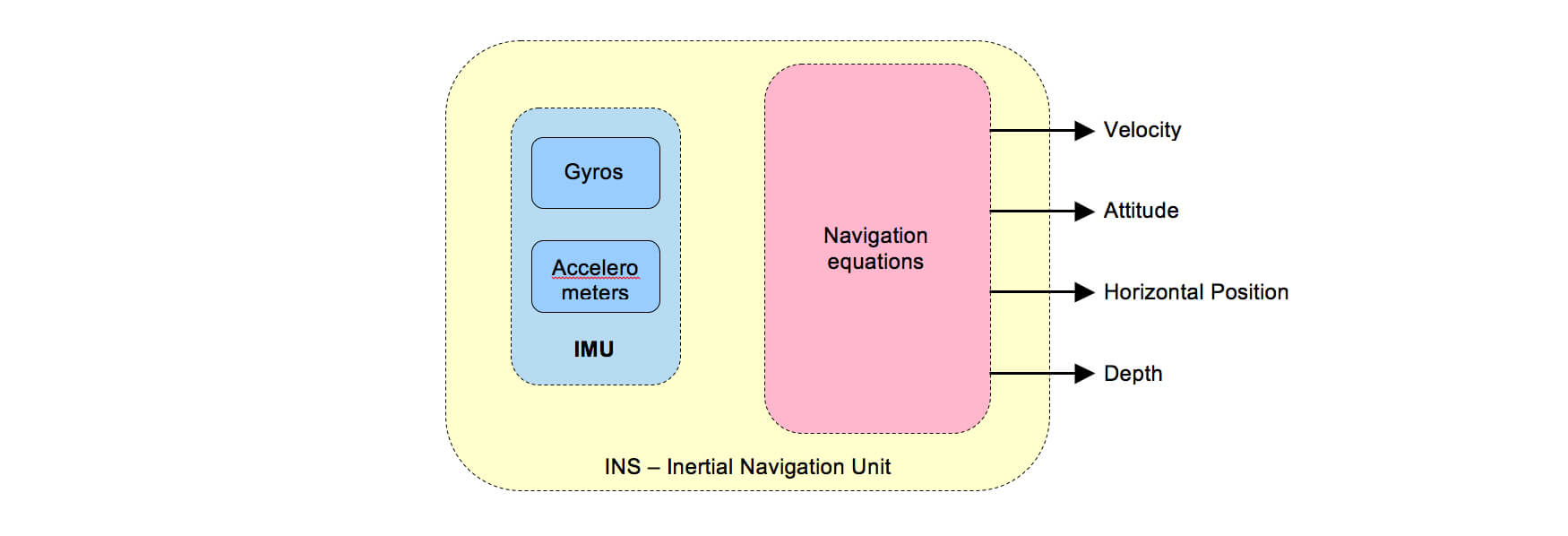
The whole arrangement is generally called a gimballed platform. Find on your left an example of an Inertial Measuring Unit (IMU), which houses not only the gyros, motors, gimbals but also the accelerometers.
Simplified Operation
As said before; the IMU is an electro-mechanical device consisting of accelerometers and gyroscopes. The accelerometers are mounted on a gimballed platform in a way that the axes of the devices sensitive to acceleration were mutually perpendicular.
At the beginning of the flight, an IMU is aligned although some say too quickly that the INS is aligned. Just to make sure; INS is a system, comprising all the components together like the IMU(s), Mode Selector Panel(s), CDUs (Control Display Unit) etc. The pilots provide the CDU with the current position of the aircraft. The system stores this information and aligns the gimballed platform to a set attitude with reference to the Earth.
The gyroscopes were set up to measure the rotational displacement and velocity of the aircraft about the longitudinal, vertical and lateral axis of the aircraft. Basically, what happens is that the gyroscope signals are used to mechanically rotate the gimbaled platform in a direction opposite to what the aircraft is doing.
This maintains the accelerometers in the same attitude relative to the Earth that they were established in during the alignment process. Thus, if one accelerometer was aligned East-West, and one North-South, this alignment would be maintained no matter the attitude of the aircraft.
The accelerometers would generate signals proportional to the accelerations in the E-W and N-S directions. This acceleration data can be directly integrated once to get velocities in the E-W and N-S directions, and integrated once more to get displacements or navigation data in the E-W and N-S directions.
Good, I hope you’re still with me? Parts of the above are derived from the Aalborg University, department of Electronic System, AeroStudents.Com, but there’s so much more on the Internet.
Let’s move on to the XP10 installation and documentation.
The xCIVA INS Add-On
Although I’ve mentioned it before, highlighting it once more can’t be a problem. The X-Plane developed CIVA INS can be found at the dedicated X-Plane.Org web page. According to X-Plane.Org, “The original CIVA INS could be found on the Boeings 707, 727, some 737-100s and -200s, the DC-10 and L-1011 Tristar, and on the early 747-100, -200 and -300 variants.
This simulated CIVA INS unit has primarily been developed to be used with the 727 series of FlyJSim however, it can be installed with any other aircraft.”
The CIVA INS package comes with the following features:
– Fully compatible with the 727 Series by FlyJSim
– Realistic warm-up, initialization and alignment procedures
– Optional Quick-Align to get you flying instantly
– All display modes modeled, including HOLD modes:
– Automatic navigation of up to 9 waypoints
– XP flight plans can be loaded instead of manual WP entry
– Single-DME updating incorporating DME elevation
– Realistic position drift and smooth updating
– Built-in 30-minute backup battery in case of emergency
Not mentioned on the dedicated X-Plane.Org CIVA INS product page, I can add to this that the CIVA INS add-on can also be used in combination with the VFW 614.
Package and User Guide
Ok, suppose that after reading this review you’ve also become enthusiastic about the CIVA INS add-on, and decided to buy your personal CIVA INS copy for only 10.00 USD, it’s time to see what you get. So, you’ve downloaded (xciva.zip | 3.9MB) and unzipped it. You end up with a folder “xciva” that contains:
– the actual plugin xciva (32/64 bit XP)
– CIVA-User-Guide.pfd
The CIVA User Guide comes among a few other chapters with:
– Inertial Navigation – An Introduction
– Installation
– The CIVA Popup window (via XP menu)
– Keyboard entry, basic modes and navigating
– The Hard mode (Cold & Dark situation)
– Display modes
– Leg change and DME updating
Although the manual seems to offer all the information what is needed to understand CIVA INS, it’s in my opinion not in a user-friendly way written. This is for example with chapter 8, which is far too much text and hardly any pictures to highlight certain process changes or visualize the steps to be taken.
Installation
Next step; where to install it?
When you use the CIVA INS in combination with the VFW 614, then it’s quite simple. Install the “xciva” folder in the X-Plane “Aircraft/PA_VFW614/plugins.
Now you can either follow the steps as discussed in my second test flight where I showed you how to use the VFW INS with CIVA INS capabilities. That was the example where the build in VFW INS gets a lot of the CIVA INS functions.
When you prefer to use the popup xCIVA INS, then go to the X-Plane Plugins menu and select CIVA. A sub popup window appears with only two options; Show/Hide. When there’s no CDU in view, you (logically) click Show. And here you are, the floating CIVA INS add-on. Personally, I had hoped as I’ve seen with the latest FlyJSim 727 update, that the xCIVA INS was placed at the position where the VFW INS unit was mounted. This would give it an even more realistic look and feel.


That’s it. The quick start guide page 14 offers you some information what’s functional and what’s not in relation to the VFW 614, and hopefully the CIVA manual will help you further in how to use this popup CIVA INS CDU. Or even better would be, Peter Aircraft comes with a step-by-step procedure how to set up this CIVA INS and how to use it.
INS Videos
Searching YouTube for the CIVA INS operation, I found four movies that could be of interest. These videos show you a different INS CDU, not the one developed for X-Plane, but it should give you a better understanding how to handle this INS CDU and the Mode Selector Unit.
– CIVA INS tutorial I
– CIVA INS tutorial II
– CIVA INS tutorial III
– CIVA INS tutorial IV
After Landing Check
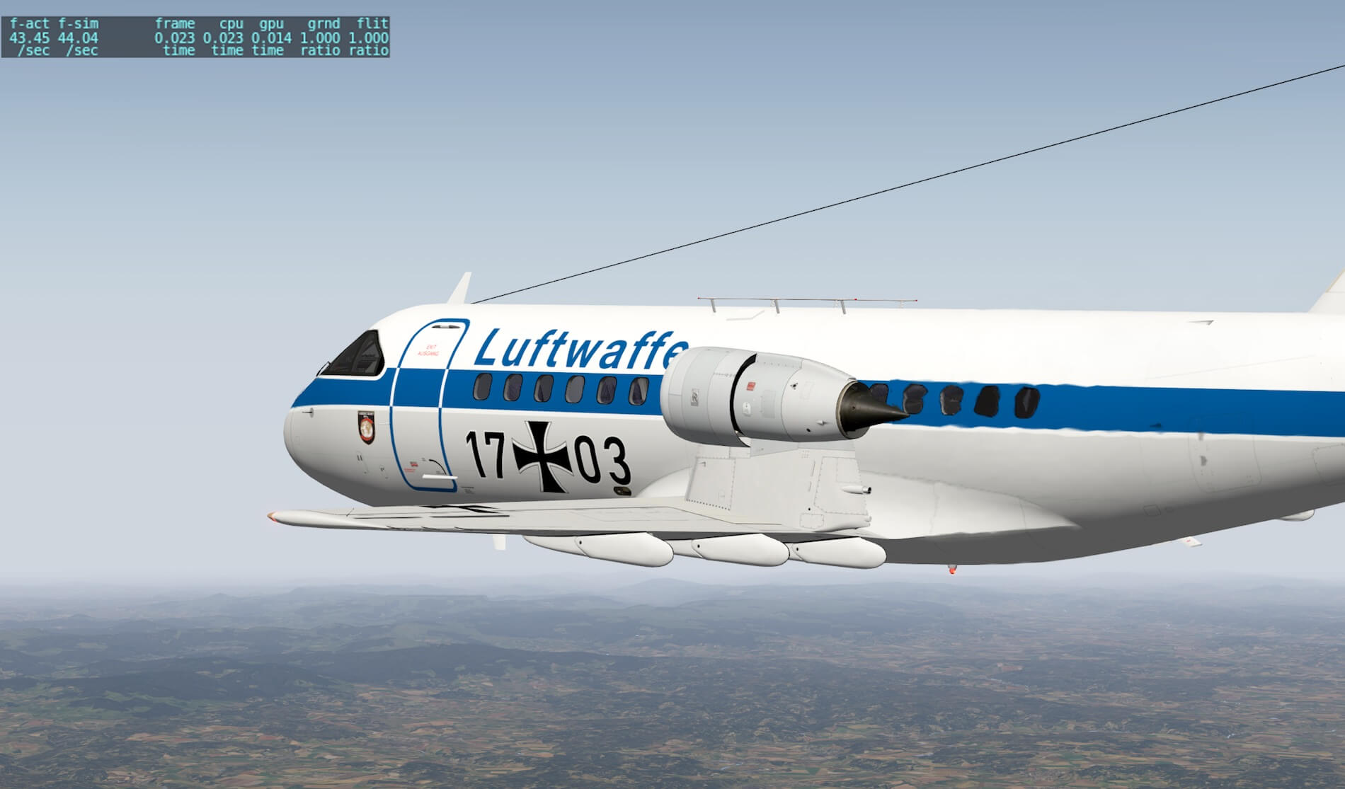
Even real pilots need to check their aircraft after landing. I’m aware that in most cases ground engineers take their share, but with some airliners, pilots have to do the walk-around check after landing. That said, it’s time to check the modeled 3D external model by me as virtual pilot.
As I mentioned before, some doors are simulated, for example the cargo- and side loading doors aren’t functional. The modeled aircraft by Peter Hager does look like a VFW 614, no doubt about that. There’s absolutely no need to verify this with real pictures and/or drawings. but first, the walk-around check.
With the passenger door opened, I do my walk-around check starting at the nose of the fuselage. The first thing that got my attention is the lack of 3D effect and the absence of NML (Normal Mapping Layer) files. After a quick check, it turned out that there’s indeed no NML file in the objects folder which explains why the fuselage, wing and tail skins are flat. It skin looks almost like that of an egg shell.
The aircraft skin texture files and the ones of the engine nacelle and fuselage, do have lines that indicate the Aluminum skin plates and/or panels. I contacted Peter about my thoughts and he’s aware of this, but not sure if it will lead to changes. I must add to this section that the dull skin effect is only applicable when using the aircraft with X-Plane 10.51+, not for X-Plane 11. The build in X-Plane 11 glossy effect gives the aircraft what’s needed however the absence of NML files stays applicable for both simulator versions.
While walking along the passenger entry door with stair – very well made by the way – I spot the engine with nacelle. Although the engine skin and that of the nacelle is very clean, I can imagine that was on the real aircraft too which can be confirmed with real photos. The overall wing is looking OK to me as well as the main landing gears, but the wheel assembly and landing gear struts are a little too clean. Those aircraft parts can be this clean, but then it’s just replaced else it’s dirty before you know. But it must be said the landing gears in general show well skilled 3D modeling.


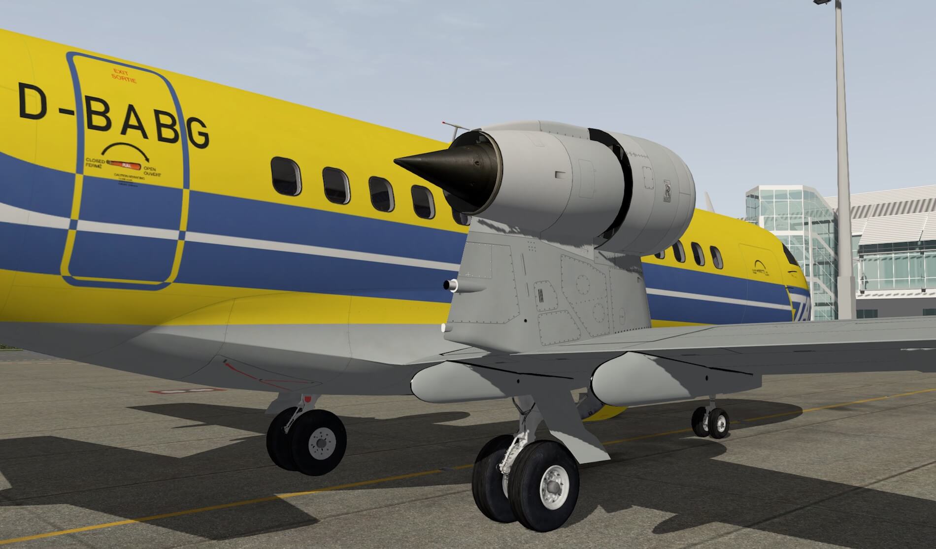
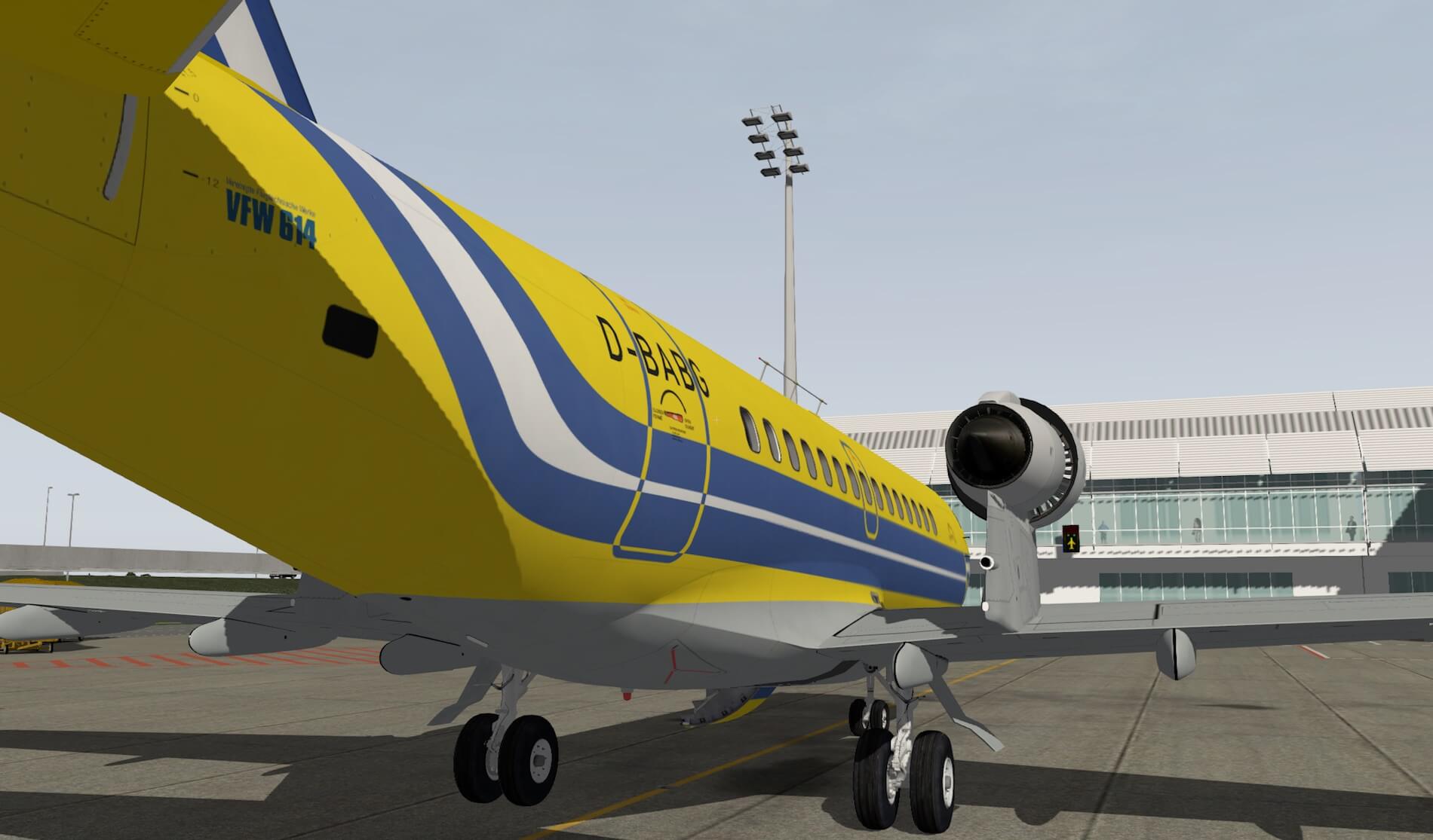
From the wing tip with – included – the static dischargers. I walk towards the wing while I had before extended the flaps. Nothing unusual to see right here. Up to the tail of the aircraft, but once more a quick look to the engine. It looks weird, an engine on top of the wing, but what’s more important is the 3D modeling and the textures. You can clearly see the difference between the engine pylon and cowling.
What else?
Clearly visible are the Aluminum skin plates, at some places the rivets and/or screws as well as the many inspection panels. I was wondering where you should find the APU outlet. I expected this at the end of the tail cone, but I think it’s located on the right hand of the fuselage in-between the AFT cargo door and the horizontal stabilizer leading edge.
It’s not a hole as I would expect, but just a black square. Looking up to the vertical fin with rudder, horizontal stabilizer with elevators, I’m pleased with what I see, but a little more weathered on the skin plates would be welcome. It feels now that the aircraft is brand new and has never flown. This is unreal and yes, I’m also aware that some airliners, even these days, polish and/or clean their aircraft several times a week, but that is rare.


Via the right-hand wing and fuselage, I walk back to the nose landing gear and end my walk-around check. Besides the few things I noted in this section, I must say that it’s a good replica of the VFW 614.
VFW 614 Walk-Arounds
The following is, as far as I understand, something new and added to the VFW 614 for the first time. According to Peter “Walk-arounds ….. action proceeds (commands) while you hold the button. Release of the button will pause the action, and you can look around with the usual view controls. Another push and hold of the button will reset you view heading, if necessary, and continue the action. Be aware that all custom view and walk-around commands are defined as INTERNAL 3D VIEW, even if your location is outside of the aircraft.”
What is this all about?
In the quick start manual, starting on page 10 section “walk-arounds”, you’ll find commands that can be assigned to either a keyboard key combination or a joystick button and let you do an action like “A specific command/action puts you on the ground outside of the aircraft, 10m sideward of the main door. Then you proceed toward the door. With the door already open and stairs down, you will directly move to the stairs and board the aircraft. With the door shut, you will proceed to open the door handle and step aside to the door actuator panel (not visible) and watch the door and stairs come down. The you will board the plane. The action stops when you reach the aisle. Then use another button command to proceed.”
Quite interesting, isn’t it? Worth to give it a shot?
To test this out, I’m curious to the command/action com/petersaircraft/airbus/enter_ac. I assign a button on my joystick for this command and see what happens. I could decide to sit and wait in the 3D cockpit at start-up of the simulator since the command puts me outside the aircraft, but I could also decide to position myself outside the aircraft (keyboard key C) and see what happens. In both cases, it works as expected. Suppose I sit in the cockpit, activating the assigned command puts me outside. When I’ve decided to wait outside, the command and actions that come, will point me to the stair and allow me to take the stair into the cabin. Although this is only one example, the quick start manual offers more commands.
And at the End
And, as usual … did I cover everything?
Perhaps not. It’s always balancing between what’s needed, what flaws do I see, what can be better, what’s gorgeous etc. In this summery, you’ll get a collection of issues/items I mentioned throughout the review. That said, it’s a nice aircraft, ok, it’s old-fashioned and you like the aircraft model or not, but it’s absolutely worth to be in your hangar.
However, issues that I mentioned need to be solved or action to be taken. It’s finally up to the developer if these suggestions and/or issues are solved. So, this section concludes a comprehensive review of Peters Aircraft VFW 614 and yes, I’m happy with this old-fashioned aircraft.
Hopefully, a paint kit will be released soon. Simmers always want to paint their own fictional livery and besides that, the factory liveries aren’t included.
Another item I noticed is that the aircraft doesn’t come with any ground equipment. The reason to bring this up is because other developers do add extra ground equipment objects. It has nothing to do with the VFW 614 product, it’s just what do you get for your money?
What else?
I highlighted the missing 3D effect because of the absence of NML files (Normal Mapping Layer) on the aircraft skin. The modeled aircraft is, as far as I’ve understood from Peter, based on the Luftwaffe model, and they were proud on their aircraft. Maintenance personal tried to keep the Luftwaffe VFW 614 as new as possible, but that doesn’t mean that weathering is something that comes quickly in time. That “weathering” is something you hardly find on this model. I sincerely hope that this will be implemented with future updates.
It would have been a good idea when Peters Aircraft had decided to include a quick tutorial how to operation/control the build in VFW INS equipment. A more extensive description would be more then welcome and I think it’s also a good idea to split the VFW INS from the CIVA INS. Mixing these INS units together as it is now in the guide, is not good. It leads quickly to confusions and why so many words about how to use the CIVA INS while it’s not a part of the VFW 614 package?
For this impression, I used, besides Peters Aircraft VFW 614, the following payware and/or freeware add-ons:
– Payware EDDL Dusseldorf Airport by Aerosoft or X-Plane.Org
– Freeware EDDM Franz Josef Strauss International Airport version 4.01 from Schaeble
I tested and flew Fokker-VFW 614 version 1.4 with no plugin installed except the plugin needed for my weather generation. Testing was done on an iMac with macOS Sierra 10.12.3 and X-Plane 10.51. When you like old-fashioned aircraft then this is a worthy add-on, that is also compatible with X-Plane 11pb15+. The way the aircraft functions and behaves isn’t so much different with X-Plane 11, but what’s different is the external look of the fuselage, wings and tail. It does have the famous glossy look. Anyway, the glossy look the VFW614 gets with X-Plane 11 is very nice, although the absence of NML files means that the VFW 614 doesn’t have that 3D effect either.
For many add-on aircraft models, I’ve seen “X-Plane 10 skin reflection packs”, but not yet for the VFW 614. Perhaps that will come after this review has been published.
More information about Peters Aircraft Fokker-VFW 614 can be found at the dedicated X-Plane.Org store page. As of this writing, the product cost you 33.00 USD. Keep in mind that this is without the additional CIVA Navigation System add-on. For more information about the CIVA INS you can have a look at the CIVA Org web page.
Feel free to contact me if you’ve got additional questions related to this impression. You can reach me via email Angelique.van.Campen@gmail.com or to Angelique@X-Plained.com.
With Greetings,
Angelique van Campen
| Add-on: | Payware Fokker-VFW 614 |
|---|---|
| Publisher | Developer: | X-Plane.Org | Peters Aircraft |
| Description: | Realistic rendition of the Fokker-VFW 614 |
| Software Source / Size: | Download / Approximately 744MB (unzipped) |
| Reviewed by: | Angelique van Campen |
| Published: | March 23th 2017 |
| Hardware specifications: | - iMac 27″ 3.5Ghz Late 2013 - Intel i7 3.5Ghz / 3.9Ghz during Boost Mode - NVIDIA GeForce GTX 780M 4096 MB - 32 GB 1600 MHz DDR3 - 1 internal 1TB SSD (Sierra 10.12.3) - 3 external 1TB SSDs - Saitek Pro Flight System |
| Software specifications: | - Sierra (10.12.3) | El Capitan (10.11.4) - Windows 10 Professional - X-Plane 10.51c | X-Plane 10.51m | X-Plane 11pb15 |
1 Comment
Submit a Comment
You must be logged in to post a comment.
Great review, I remember seeing these as a kid in the late 70’s, I would buy this if he got his A380 sorted for XP11, spending money with upgrade promises is not in my wallet anymore!